Reflection, Refraction and Fresnel
Reading time: 29 mins.Reflection, Refraction (Transmission), and Fresnel
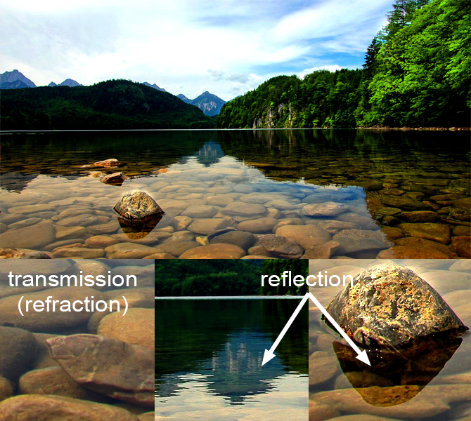
Reflection and refraction are very common in the real world and can be observed every day. Glass or water are two very common materials that exhibit both properties. Light can pass through them, a phenomenon we call transmission and they can reflect light at the same time. The important question we will need to answer in this chapter is how do we know how much light is transmitted versus how much light is reflected? To answer this question, we will need to learn about the Fresnel effect. Other materials are opaque and can not transmit any light though they can certainly reflect it very well. This is the case for example of metals.
In this chapter, we will learn about simulating reflection, refraction (transmission), and the Fresnel effect which defines for transparent materials such as glass and water how much light is reflected vs. how much light is transmitted.
Reflection
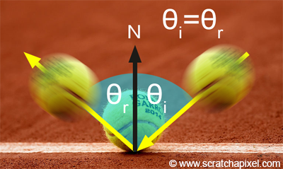
Let's start with reflection which is almost the simplest form of light-matter interaction. Reflection is the result of what happens to a photon, or an incident light beam if you are not familiar with the concept of the photon, when it hits the surface of a reflective surface such as glass, water, or a sheet of aluminum for example. What happens to this photon, is very similar to what happens to a tennis ball when it hits the surface of the floor. It bounces back in a direction that is symmetrical to the incident direction about the surface normal at the point of impact as shown in figure 1\. In other words, if the angle between the incident direction and the surface normal is denoted \(\theta_i\) and the angle between the reflected direction and the surface normal is \(\theta_r\), then \(\theta_i = \theta_r\). Simple! This is called the law of reflection.
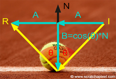
Computing the reflection direction when the incident direction and the surface normal are known is very simple. As you can see in figure 2, the vectors I and R can be expressed in terms of the vectors A and B:
$$ \begin{array}{l} I &=& A + B,\\ R &=& A - B. \end{array} $$The vector \(B\) can easily be computed. It is the projection of the vector \(I\) or \(R\) onto the vector \(N\). As explained in the lesson on geometry, this can be computed using the following equation:
$$B = \cos(\theta) * N.$$The term \(\cos(\theta)\) is of course equal to: \(N.I\). It is the dot product between \(N\) and \(I\).
We can now replace \(B\) in both equations:
$$ \begin{array}{l} I &=& A + \cos(\theta) * N,\\ R &=& A - \cos(\theta) * N. \end{array} $$We can re-write the first equation as follows:
$$A = I - \cos(\theta) * N.$$We can write the second equation using this result as follows:
$$ \begin{array}{l} R &=& I - \cos(\theta) * N - \cos(\theta) * N,\\ R &=& I - 2\cos(\theta) N,\\ R &=& I - 2(N \cdot I)N. \end{array} $$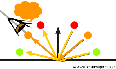
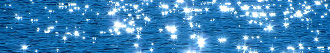
A reflection of a light ray can only be seen if the reflected ray direction is traveling in the same direction as the view direction. In figure 3, you can see the reflection of three rays with distinct incident directions and distinct colors. While the light beams intersect the surface at the same point on the surface, the observer will only see the reflection of the ray in the middle (the ray with the orange color). If you fix the view direction and change the direction of the incident ray in the middle even just slightly, then the observer will stop seeing the reflection of that ray. To see the reflection of the ray again, the observer would need to change his/her position to align his/her view direction with the direction of the orange reflected ray. If the direction of the incident is fixed but the observer moves, then if the view direction is aligned with the reflection direction of the red, orange, and green reflected ray successively, then the viewer would see in turn a red, orange, and then green point on the surface of the object. This is very similar to what happens when we observe the reflection of the sun on a wavy water surface. We can see the reflection of the sun when the angle of the wave with respect to the viewer is right but because the shape of the wave changes rapidly the reflection can appear as well as disappear quickly (glittering effect).
The fact that the reflected image of the objects in the scene from which these light rays are emitted changes with the view direction is the reason why we say that reflection is view-dependent. If you look at the reflection of a static object in the mirror and change direction, you will see that the image of that object changes. This is something that we find natural when we look at an object from a different angle, but that we find maybe less natural when we change our position with respect to a mirror reflecting that same object, though the reason why this is happening is essentially the same. We look at a different part of the object. By opposition, we say that diffuse reflections are view independent because they don't vary with the angle of view as explained in the chapter on Lambertian material.
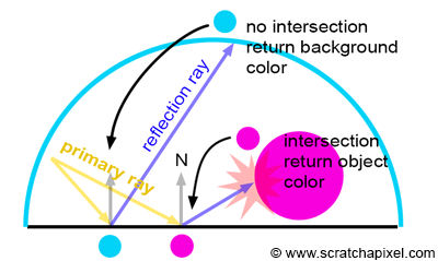
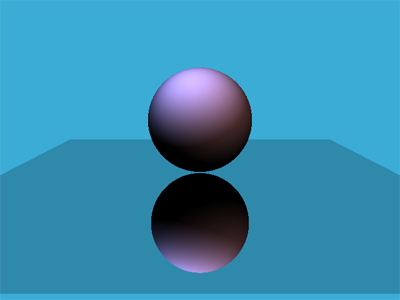
Simulating reflection in our ray tracer is very simple. If the object that the primary ray hit is a mirror-like surface, then we compute the reflection direction using the incident view direction (the primary ray direction) and the normal of the surface at the intersection point. We then call the castRay() function recursively (the function calls itself) and assign to the primary ray color the color of the reflected ray. The reflection ray can be called a reflection or also sometimes a specular ray (we will explain what the term specular means in more detail in the next chapter). Note that this technique can only produce perfectly sharp reflections. To learn how to produce blurry or glossy reflections, please refer to the next chapter or the second lesson on shading from this section. Because the plane in our example reflects the background color when it doesn't reflect the sphere, the plane and the background image wouldn't visually be distinguishable from each other. For this reason, we reduce the brightness of the reflection by a small amount (20% in our example - line 24). This is not wrong, as mirror like surfaces generally never reflect 100% of the incident light anyway. The Fresnel effect which we will talk about later in this chapter can also have an effect on how much light a surface reflects.
Vec3f reflect(const Vec3f &I, const Vec3f &N)
{
    return I - 2 * dotProduct(I, N) * N;
}

Vec3f castRay(
    const Vec3f &orig, const Vec3f &dir,
    const std::vector<std::unique_ptr<Object>> &objects,
    const std::vector<std::unique_ptr<Light>> &lights,
    const Options &options,
    const uint32_t & depth = 0)
{
    if (depth > options.maxDepth) return options.backgroundColor;
    ...
    if (trace(orig, dir, objects, isect)) {
        ...
        switch (isect.hitObject->type) {
            case kDiffuse:
            ...
            case kReflection:
            {
                Vec3f R = reflect(dir, hitNormal);
                hitColor += 0.8 * castRay(hitPoint + hitNormal * options.bias, R, objects, lights, options, depth + 1);
                break;
            }
            ...
        }
    }
    ...

    return hitColor;
}
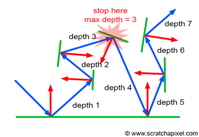
Note that the process is potentially recursive. It is entirely possible to have a situation in which a ray intersects a reflective surface from which we cast another reflection ray, that will intersect in turn another reflective surface, etc. In other words, the process will keep casting reflection rays unless the ray intersects an object which is not a mirror or if it doesn't intersect anything at all (in which case we return the background color). If a ray kept reflecting other reflecting surfaces without ever reflecting anything else, we would then enter some kind of infinite recursive process. To prevent this from happening, we generally put a cap or limit on the number of recursions. The number of times a reflection ray is reflected off of surfaces is called the ray depth. When we cast a reflection ray from the primary ray, we say that the ray has a depth of 1. After two reflections, the ray has a depth of 2, and so on. The ray depth is incremented each time we call the castRay() function recursively. At the beginning of the function (line 14), we test whether the ray depth is greater than the maximum ray depth allowed. If this is the case, we stop from going any further in the execution of the function and simply return the background color (as if the ray had not intersected any object at all). Of course, introducing this cap means that our produced image will deviate from reality. Though for most scenes using a depth much greater than 4 or 5 generally doesn't make much of a visual difference. It's only when very complex transparent surfaces are rendered (such as water splashes) that using a depth much greater than 5 is necessary for producing images that are similar to the real thing. But these cases are hopefully generally rare. Keep in mind that another reason for putting a cap on the recursion depth is also because ray tracing is expensive. The higher the recursion the longer it will take to render a frame. Setting the maximum recursion depth is always a trade-off between image quality and render time.
Note that reflection (as many of the other shading effects we will study from now on) can be perfectly simulated with the ray-tracing algorithm. Remember that ray tracing is essentially a technique for computing the visibility between two points. In this particular case, we compute the visibility between the point from which the ray is cast to the first surface where the ray intersects in the ray's direction (the reflection direction in this example). This is primarily why ray tracing is better than rasterization for example when it comes to simulating effects such as reflection.
Refraction
In this lesson, we will only deal with the case of clear transparent objects. For many transparent objects, light is attenuated as it travels through the medium. In this lesson, we will ignore the effect of light attenuation and absorption by a medium. You will find information on this effect in the advanced lessons on shading.
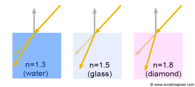
When light rays pass from one "transparent" medium to another, they change direction. This phenomenon is illustrated in figure 7\. As you can see the light ray represented in this figure is bent at the boundary or interface between the two mediums (this can be air-glass, air-water, glass-water, etc.). The new direction of the ray depends on two factors. The ray angle of incidence and the new medium refractive index or index of refraction (also sometimes referred to as ior). The index of refraction for glass and water is around 1.5 and 1.3 respectively. For a fixed angle of incidence, the amount of bending depends on the index of refraction. (as shown in the image below).
When light travels in a vacuum, we all know that it travels at the speed of light which is often denoted by the constant \(c\). But when it travels through another medium, its speed decreases. If we denote the speed of light in this medium \(v\), then the index of refraction is simply the ratio of \(c\) over \(v\):
$$\eta= \dfrac{c}{v}.$$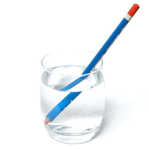
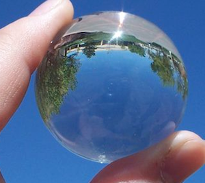
Refraction indices are generally denoted with the letter \(\eta\) (the Greek letter eta). Light travels faster in water than in glass, but slower than in air (air has a refractive index very close to 1 and in CG we almost always treat air as if it was a vacuum). Refraction or the bending of light rays explains why objects seen through transparent objects such as glass or water, look deformed. It can create some really strange effects such as the illusion of a broken pen shown in Figure 8. Looking at objects through a glass ball can inverse the image of the objects seen through the ball as shown in Figure 9. These are some effects caused by refraction (which fits into the category of optical effects). Explaining the phenomenon of refraction is beyond the scope of this lesson. We will just stick for now to the equation that can be used to compute the refracted ray direction.
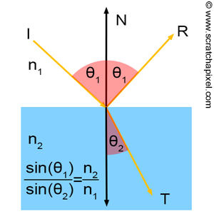
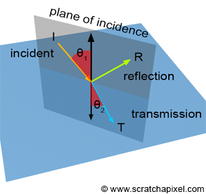
Refraction is described by Snell's law, which states that for a given pair of media, the ratio of the sines of the angle of incidence \(\theta_1\) and angle of refraction \(\theta_1\) is equivalent to the opposite ratio of the indices of refraction (figure 7):
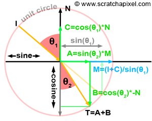
$$\dfrac{\sin\theta_1}{\sin\theta_2} = \dfrac{\eta_2}{\eta_1}.$$As you can see, the equation is really simple. We already know \(\theta_1\), is the dot product between the incident ray direction and the surface normal as well as the refraction indices. Although how does it work in 3D space? If you look at Figure 10, you can see that the incident ray, the reflected ray, and the transmitted ray all lie in the same plane which is called the plane of incidence (in this plane lies the incident ray and the surface normal). In other words, we can think in terms of geometric construction in the plane of incidence. Look at Figure 11. First, you can see that the vector \(T\) the transmission ray that we want to build, is the sum of the vector \(A\) and \(B\)
$$T = A + B.$$\(A\) and \(B\) can easily be computed using the following two equations:
$$ \begin{array}{l} A = M\sin(\theta_2),\\ B = -N\cos(\theta_2). \end{array} $$We already know about \(N\) but what about vector \(M\)? Well, this vector can also be easily found by construction. You can see that \(M\) can be computed as follows:
$$M = \dfrac{(I + C)}{\sin(\theta_1)}.$$The first part of the equation is simple. The term \(I + C\) gives a vector perpendicular to \(N\) or if you prefer to say it differently, tangent to the surface. Though this vector is normalized. To normalize it, you just need to divide it by \(\sin(\theta_1\)). You can see that the length of \(I + C\) is exactly equal to \(\sin(\theta_1)\). If the length of the unnormalized vector is 0.7 and you divide it by 0.7, its length after the division will be 1\. The vector will be normalized. We have \(M\) and \(N\). The vector \(C\) is simply equal as usual to:
$$C = \cos(\theta_1)N.$$If we put all these elements together we get:
$$ \begin{array}{l} T = A + B,\\ T = M\sin(\theta_2) - N\cos(\theta_2),\\ T = \dfrac{(I + C)\sin(\theta_2)}{\sin(\theta_1)} - N\cos(\theta_2),\\ T = \dfrac{(I + \cos(\theta_1)N)\sin(\theta_2)}{\sin(\theta_1)} - N\cos(\theta_2). \end{array} $$We know that (Snell's law):
$$\dfrac{\sin(\theta_2)}{\sin(\theta_1)} = \dfrac{\eta_1}{\eta_2}.$$Thus:
$$T = \dfrac{\eta_1}{\eta_2}(I + \cos(\theta_1)N) - N\cos(\theta_2).$$We also know that:
$$\cos^2(\theta) + \sin^2(\theta) = 1 \rightarrow \cos(\theta) = \sqrt{1 - \sin^2(\theta)}.$$And since:
$$\sin(\theta_2) = \dfrac{\eta_1}{\eta_2} \sin(\theta_1).$$We finally have:
$$T = \dfrac{\eta_1}{\eta_2}(I + \cos(\theta_1)N) - N\sqrt{1 - \left( \dfrac{\eta_1}{\eta_2} \right) ^2 \sin^2(\theta_1)}.$$If we write:
$$ \begin{array}{l} \eta = \dfrac{\eta_1}{\eta_2},\\ c_1 = \cos(\theta_1) = N \cdot I,\\ c_2 = \sqrt{1 - \left( \dfrac{n_1}{n_2} \right) ^2 \sin^2(\theta_1)} \rightarrow \sqrt{1 - \left( \dfrac{n_1}{n_2} \right) ^2 (1 - \cos^2(\theta_1))} \end{array} $$Then:
$$ \begin{array}{l} T = \eta(I + c_1 N) - N c_2,\\ T = \eta I + (\eta c_1 - c_2) N. \end{array} $$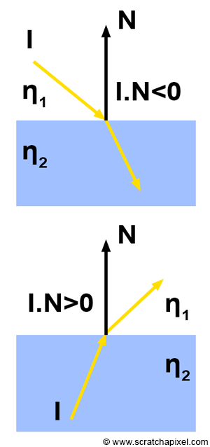
Maybe you should take a moment to contemplate the beauty of nature (and of mathematics). It was quite astonishing to think that light follows such simple mathematic geometric rules and yet, what causes the phenomenon of refraction is quite a complex physical effect. Congratulations, you now can compute the direction of the refracted ray. There are a couple of details we need to take care of in the actual implementation of this equation. First, in some cases, the ray will hit the surface from outside. This is the case when the light ray enters a volume of water for example. But when the ray leaves that volume of water, the normal will be pointing on the other side of the water surface. In this particular case if we want our equation to work we will need to invert the normal direction. Finding if the incident ray hits the surface from outside or inside can simply be done by checking the sign of the dot product between the normal and the incident ray direction (as shown in figure 12). Keep in mind that the result of \(\cos(\theta_1\)) also needs to be positive. If it is negative (if the incident ray hits the surface from outside) we will need to reverse the sign of the dot product. Finally, keep in mind that \(\eta_1\) and \(\eta_2\) are the refraction indices of the first and second medium respectively. If the ray leaves the second medium and enters the first one, we will need to inverse the order of the two medium refraction index to compute \(\eta\).
Vec3f refract(const Vec3f &I, const Vec3f &N, const float &ior)
{
    Vec3f Nrefr = N;
    float NdotI = Nrefr.dotProduct(I);
    float etai = 1, etat = ior; // etai is the index of refraction of the medium the ray is in before entering the second medium
    if (NdotI < 0) {
        // we are outside the surface, we want cos(theta) to be positive
        NdotI = -NdotI;
    }
    else {
        // we are inside the surface, cos(theta) is already positive but reverse normal direction
        Nrefr = -N;
        // swap the refraction indices
        std::swap(etai, etat);
    }
    float eta = etai / etat; // n_1 / n_2
    ...
}
In this particular piece of code, ior is the refraction index of the material of the physical object the ray has either hit or is about to leave (glass, water, etc.). As stated before air has a refraction index close to 1, and for this reason, in CG, we generally ignore it. We treat air as if it was a vacuum.
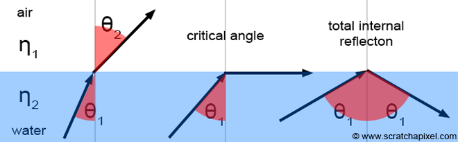
One final detail needs to be accounted for. When the angle of the incident is greater than some value called the critical angle, then 100% of the light incident on the surface is reflected. In another word, when the angle of the incident is greater than the critical angle, there isn't any refraction at all. This only happens though when the light ray passes from one medium to another medium with a lower index of refraction, such as in the case of a water-air, diamond-water, or glass-water interaction. This phenomenon is called total internal reflection.
We can compute this angle if desired, though when we compute the refraction direction, there is a simpler way of knowing when this happens. It happens when the term within the square root of the term \(c_2\) is negative (the square root, in this case, is a negative number or imaginary):
Vec3f refract(const Vec3f &I, const Vec3f &N, const float &ior)
{
    Vec3f Nrefr = N;
    ...
    float k = 1 - eta * eta * (1 - cosi * cosi);
    if (k < 0)
        // total internal reflection. There is no refraction in this case
        return 0;
    else
        eta * I + (eta * NdotI - sqrtf(k)) * Nrefr ;
}
There is another way of computing or finding out when the incident light is reflected rather than being refracted. You need to compute the sine of the angle of refraction. If \(\sin\theta_2\) is greater than 1, then we have a case of total internal reflection. Note that this value can easily be computed using Snell's law:
float sint = etai / etat * sqrtf(std::max(0.f, 1 - cosi * cosi));
Finally here is a complete implementation of the refraction function:
Vec3f refract(const Vec3f &I, const Vec3f &N, const float &ior)
{
    float cosi = clamp(-1, 1, dotProduct(I, N));
    float etai = 1, etat = ior;
    Vec3f n = N;
    if (cosi < 0) { cosi = -cosi; } else { std::swap(etai, etat); n= -N; }
    float eta = etai / etat;
    float k = 1 - eta * eta * (1 - cosi * cosi);
    return k < 0 ? 0 : eta * I + (eta * cosi - sqrtf(k)) * n;
}
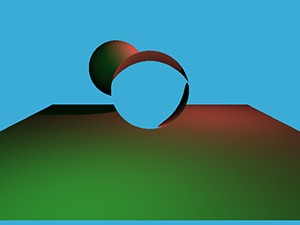
You can see a render of a glass sphere on the right. As in the example of the real glass ball from figure 9, you can see that the image of the background geometry is inverted in the sphere. If you follow the path of the refracted rays through the ball, you will understand why. The problem with this image though, is that it is not completely realistic. Glass spheres as well as pretty much every other transparent surface (water, diamonds, crystals, etc.) transmit as well as reflect light. They are both refractive and reflective. The problem is how do we know how much light they transmit vs. the amount of light they reflect? This ratio is given by the Fresnel equations which we will study next.
Fresnel
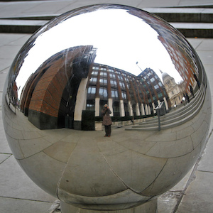
As mentioned just above, transparent objects such as glass or water are both refractive and reflective. How much light they reflect vs the amount they transmit depends on the angle of incidence. The amount of transmitted light increases when the angle of incidence decreases. And since by the principle of the conservation of energy, the amount of reflected light plus the amount of refracted light is necessarily equal to the total amount of incident light, you can deduce that the amount of reflected light increases when the angle of incidence increases, up to 100% as the angle gets closer to 90 degrees. Technically, the edges of a glass ball are 100% reflective. In its center though, the sphere only reflects about 6% of the incident light.
The amount of reflected vs. refracted light can be computed using what we call the Fresnel equations. Explaining the origin of these equations and how they can be derived goes far beyond the level of explanation we are willing to give in this lesson. Light is composed of two perpendicular waves which we call parallel and perpendicular polarised light. Don't worry too much if you don't know about this detail. Suffice it to know that we need to compute the ratio of reflected light for these two waves using two different equations (one for each type of wave) and average the results to find the solution. The two Fresnel equations are:
$$ \begin{array}{l} F_{R\parallel} = \left( \dfrac{\eta_2 \cos\theta_1 - \eta_1 \cos \theta_2}{\eta_2 \cos\theta_1 + \eta_1 \cos \theta_2} \right)^2,\\ F_{R\perp} = \left( \dfrac{\eta_1 \cos\theta_2 - \eta_2 \cos \theta_1}{\eta_1 \cos\theta_2 + \eta_2 \cos \theta_1} \right)^2. \end{array} $$By taking the average of the two we get the actual ratio of reflected light:
$$F_R = \dfrac{1}{2}(F_{R\parallel} + F_{R\perp}).$$The terms \(\eta_1\), \(\eta_2\) are the refraction indices of the two mediums. The terms \(\cos\theta_1\) and \(\cos\theta_2\) are the angles of incidence and refraction respectively. As mentioned before, due to the conservation of energy, the ratio of refracted light can simply be computed as:
$$F_T = 1 - F_R.$$Keep in mind that if the light goes from one medium to another medium with a lower refraction index, it may be subject to the phenomenon of total internal reflection. This is happening in the case of materials such as glass or water, so we need to take this into account. We do so by computing as in the case of reflection, the sine of the angle of refraction or \(\theta_2\). If \(\sin\theta_2\) is greater than 1, then we have a case of total reflection. In this particular case, there is no need to compute the Fresnels formulas. We can just set \(F_R\) to 1\. As usual, you will need to swap the refraction indices if you find out that the incident ray is inside the object with the greatest refraction index. This can be done again by testing the sign of the cosine of the angle between the surface normal and the incident ray direction (the sign of \(\cos\theta_1\)). Here is a possible implementation of the Fresnel formula:
void fresnel(const Vec3f &I, const Vec3f &N, const float &ior, float &kr)
{
    float cosi = clamp(-1, 1, dotProduct(I, N));
    float etai = 1, etat = ior;
    if (cosi > 0) { std::swap(etai, etat); }
    // Compute sini using Snell's law
    float sint = etai / etat * sqrtf(std::max(0.f, 1 - cosi * cosi));
    // Total internal reflection
    if (sint >= 1) {
        kr = 1;
    }
    else {
        float cost = sqrtf(std::max(0.f, 1 - sint * sint));
        cosi = fabsf(cosi);
        float Rs = ((etat * cosi) - (etai * cost)) / ((etat * cosi) + (etai * cost));
        float Rp = ((etai * cosi) - (etat * cost)) / ((etai * cosi) + (etat * cost));
        kr = (Rs * Rs + Rp * Rp) / 2;
    }
    // As a consequence of the conservation of energy, the transmittance is given by:
    // kt = 1 - kr;
}
If you plot this function here is what the curves look like:
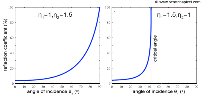
The curve on the left shows the ratio of reflected light in the case of an air-glass transition. The curve on the right shows the same ratio for a transition glass-air. As you can see, 100% of the light is reflected when we reach an angle of incidence much smaller than 90 degrees in the second cube. This is due to the phenomenon of total internal reflection.

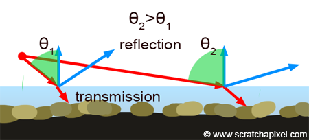
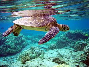
The fresnel effect can easily be observed in nature. If you look at the picture of the lake with some mountains in the background and pebbles in the foreground at the beginning of this chapter, you can see that the reflection seems to increase with distance. Note also that while reflections are strong in the distance, we see more clearly through the water in the foreground than we do in the far distance. This is due to fresnel. The angle of incidence increases with the distance as shown in figure 16, and we know that the ratio of reflection vs. transmission increases with the angle of incidence. Thus naturally as we look in the distance, the water's surface reflects more light. Though if we look almost directly down on the water surface, a few meters from where we stand, the angle incidence is low and most of the light is transmitted. Thus we see through the water more clearly than when we look in the distance. You can easily observe this effect on a large variety of objects: the facade of a building made out of glass, glass balls that are more reflective on the edges, etc.
Implementation
Let's now put everything we learned so far, and try to reproduce the image of the pen in a glass of water. For this exercise, we will just model the volume of water with a simple cylinder. To keep things simple we haven't created a model of the glass containing the volume of water. This is left as an exercise. The scene is rendered with a distance light. To keep things simple, the water volume doesn't cast a shadow. Shadow casting of transparent objects will be studied in a separate lesson. The pen is rendered using a flat shading model. The rest of the scene uses smooth shading (interpolation of vertex normals). First, we declare the volume model as both a reflective and refractive surface. We also added an ior member variable to the object class to store the object index of refraction:
TriangleMesh *mesh3 = loadPolyMeshFromFile("./cylinder.geo", Matrix44f::kIdentity);
if (mesh3 != nullptr) {
    mesh3->type = kReflectionAndRefraction;
    mesh3->ior = 1.3;
    objects.push_back(std::unique_ptr<Object>(mesh3));
}
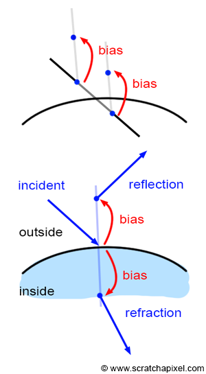
In the castRay function, we just added one case to the material switch. If the surface is both transparent, we then first compute the ratio of reflected light using the fresnel equation. Note that, as a small optimization, we only compute the transmitted light if the ratio of reflected light is lower than 1 (this is not a case of total internal reflection). The reflected and refraction rays are then computed (lines 22 and 27) and the reflected and transmitted light is computed by tracing a ray in both the reflected and refracted direction. Note that we have to add a small bias again to the ray origin to avoid the phenomenon of acne which we already described in the chapters on shadows. In the case of reflection, we need to push the point on the same side of the surface hit by the incident ray, and in the case of refraction, the points need to be pushed inward (figure 17).
The way we deal with acne in ray tracing by pushing the ray origin in the normal direction is a very naive solution to this problem. Research to address this problem has been done and can be found on the web. An ideal solution is one in which the bias can be computed automatically as opposed to being fixed for the entire scene, or fixed on an object basis.
Finally, the results are mixed using the result of the fresnel equation (line 32).
switch (isect.hitObject->type) {
    case kDiffuse:
    {
        ...
        break;
    }
    case kReflection:
    {
        ...
        break;
    }
    case kReflectionAndRefraction:
    {
        Vec3f refractionColor = 0;
        // compute fresnel
        float kr;
        fresnel(dir, hitNormal, isect.hitObject->ior, kr);
        bool outside = dir.dotProduct(hitNormal) < 0;
        Vec3f bias = options.bias * hitNormal;
        // compute refraction if it is not a case of total internal reflection
        if (kr < 1) {
            Vec3f refractionDirection = refract(dir, hitNormal, isect.hitObject->ior).normalize();
            Vec3f refractionRayOrig = outside ? hitPoint - bias : hitPoint + bias;
            refractionColor = castRay(refractionRayOrig, refractionDirection, objects, lights, options, depth + 1);
        }

        Vec3f reflectionDirection = reflect(dir, hitNormal).normalize();
        Vec3f reflectionRayOrig = outside ? hitPoint + bias : hitPoint - bias;
        Vec3f reflectionColor = castRay(reflectionRayOrig, reflectionDirection, objects, lights, options, depth + 1);

        // mix the two
        hitColor += reflectionColor * kr + refractionColor * (1 - kr);
        break;
    }
    default:
        break;
}
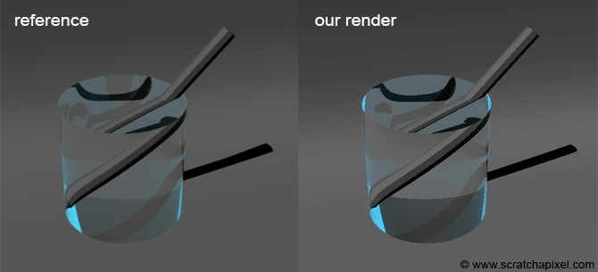
Note that the result we get is very similar to the same scene rendered with a commercial renderer (Mental Ray in this case). The difference between the two images comes from the fact that in the reference image we set the max depth to 10 while in the image on right (our render), we set the max depth limit to 4. If you set the limit to 10, you will get the same image:
options.maxDepth = 10;
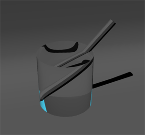
Note that the effect of the refracted pen in the water is very similar to the image in Figure 8. While subtle, the fresnel effect on the edges of the water volume is also visible. Some people don't feel that this image is photo-real. From a physical point of view, it is. If you do not simulate the internal reflections though, you get an image like the one on the rights, which might seem visually more real. This is also what the art of shading is all about. Contrary to nature, you have control over many different aspects of the simulation and by changing various settings (whether you have similar internal reflections or not, the maximum ray depth, etc.) you can control the look of the final rendered image.
Other Things You Should Know About Reflection: Conductor and Dielectric.
This is already a long chapter in which we introduced many fundamental concepts from shading. Namely, we talked about:
-
Reflection,
-
Refraction,
-
Fresnel,
-
and ray scene and bias as a side effect of using ray tracing to compute or simulate these effects.
There are many more things to say about these different effects. For example that reflections are a wavelength effect. Indeed materials do not refract the light of different wavelengths in the same way. We will study these details later. Though one thing you may want to know before we close this chapter is that metallic objects reflect light. In fact, in computer graphics, we like to classify materials into two broad categories: the dielectric materials and the conductor materials. Conductors as you may have guessed are metals. Metals too reflect light and they also reflect more light at a grazing angle. Though the fresnel equation used to reflect the ratio of reflected light by metals is different than the one we studied in this lesson which is used to simulate the fresnel effect of dielectric materials. Dielectrics are essentially nonconducting materials or electric insulators for example. In this category, you find things such as glass or plastic as well as water. Pure water is an electric insulator indeed. Remember the names conductor and dielectric as they are used a lot in shading and computer graphics.