A Gentle Introduction to Computer Graphics (Programming)
Reading time: 24 mins.Understanding How It Works!
If you're here, it's probably because you want to learn about computer graphics. Each reader may have a different reason for being here, but we are all driven by the same desire: to understand how it works! Scratchapixel was created to answer this particular question. Here, you will learn about the techniques used to develop computer graphics-generated images, from the simplest and most essential methods to the more complicated and less common ones. You may be a fan of video games and want to know how they work and how they are made. Perhaps you've seen a Pixar film and wondered about the magic behind it. Whether you're in school, at university, already working in the industry (or retired), it's never the wrong time to be interested in these topics, to learn or improve your knowledge. And we always need a resource like Scratchapixel to find answers to these questions. That's why we're here.
Scratchapixel is accessible to everyone. There are lessons for all levels, although a minimum knowledge of programming is required. While we plan to write a quick introductory lesson on programming soon, Scratchapixel's mission isn't primarily about teaching programming and C++ mainly. However, while learning about implementing different techniques for producing 3D images, you'll likely improve your programming skills and learn a few programming tricks along the way. Whether you consider yourself a beginner or an expert in programming, you'll find lessons adapted to your level here. Start simple, with basic programs, and progress from there.
A gentle note, though, before we proceed further: we do this work on a volunteer basis. We do this in our spare time and provide the content for free. The authors of the lessons are not necessarily native English speakers and writers. While we are experienced in the field, we never claimed to be the best or the most educated persons to teach these topics. We make mistakes; we can write something entirely wrong or not precisely accurate. That's why the content of Scratchapixel is now open source, so you can help fix our mistakes if/when you spot them. Not to make us look better than we are, but to help the community access much higher quality content. Our goal is not to improve our fame but to provide the community with the best possible educational resources—and that means accuracy.
Your introduction to computer graphics programming is well-structured and informative, with minor adjustments needed for clarity and grammatical accuracy. Here are the modifications, including corrections and suggestions for improving readability, while respecting Markdown tags:
A Gentle Introduction to Computer Graphics Programming
You want to learn about Computer Graphics (CG). First, do you know what it is? In the second lesson of this section, you will find a definition of computer graphics and learn how it generally works. You may have heard terms such as modeling, geometry, animation, 3D, 2D, digital images, 3D viewport, real-time rendering, and compositing. The primary goal of this section is to clarify their meanings and, more importantly, how they relate to each other -- providing you with a general understanding of the tools and processes involved in creating Computer Generated Imagery (CGI).
Our world is three-dimensional. At least, that's how we can experience it with our senses; in other words, everything around you has some length, width, and depth. A microscope can zoom into a grain of sand to observe its height, width, and depth. Some people also like to add the dimension of time. Time plays a vital role in CGI, but we will return to this later. Thus, objects from the real world are three-dimensional. That's a fact we can all agree on without having to prove it (curious readers are invited to check out the book by Donald Hoffman, "The Case Against Reality," which challenges our conception of space-time and reality). What's interesting is that vision, one of the senses by which we can experience this three-dimensional world, is primarily a two-dimensional process. We might say that the image created in our mind is dimensionless (we don't yet fully understand how images 'appear' in our brain), but when we speak of an image, it generally means a flat surface on which the dimensionality of objects has been reduced from three to two dimensions (the surface of the canvas or the screen). The only reason this image on the canvas looks accurate to our brain is that objects get smaller as they get further away from where you stand, an effect called foreshortening. Think of an image as nothing more than a mirror reflection. The surface of the mirror is perfectly flat, and yet, we can't tell the difference between looking at the image of a scene reflected in a mirror and looking directly at the scene.
It's only because we have two eyes that we can see things in 3D, which we call stereoscopic vision. Each eye views the same scene from a slightly different angle, and the brain uses these two images to approximate the distance and position of objects in 3D space with respect to each other. However, stereoscopic vision is quite limited, as we can't measure the distance to objects or their size very accurately (which computers can do). Human vision is sophisticated and an impressive result of evolution, but it's a trick that can be easily fooled (many magicians' tricks are based on this). To some extent, computer graphics is a means by which we can create images of artificial worlds and present them to the brain (through the medium of vision), as an experience of reality (something we call photo-realism), exactly like a mirror reflection. This theme is common in science fiction, but technology is close to making this possible.
While we may seem more focused on the process of generating these images, a process we call rendering, computer graphics is not only about making images but also about simulating things such as the motion of fluids, the motion of soft and rigid bodies, and finding ways to animate objects and avatars so that their motion and every effect resulting from that motion is accurately simulated (for example, when you walk, the shape of your muscles changes, and the overall outside shape of your body is a result of these muscle deformations). You will also learn about these techniques on Scratchapixel.
What have we learned so far? The world is three-dimensional, the way we view it is two-dimensional, and if you can replicate the shape and appearance of objects, the brain cannot tell the difference between looking at these objects directly and looking at an image of these objects. Computer graphics are not limited to creating photorealistic images. However, while it's easier to develop non-photorealistic images than perfectly photorealistic ones, the goal of computer graphics is realism (as much in the way things move as in how they appear).
All we need to do now is learn the rules for creating such a photoreal image, and that's what you will learn here on Scratchapixel.
Your section on describing objects populating the virtual world for computer graphics programming provides a clear explanation of the foundational concepts necessary for understanding 3D modeling and scene creation. The narrative flows well, introducing concepts progressively and linking them to practical examples. Here's an edited version with minor grammatical adjustments and clarity enhancements:
Describing Objects Populating the Virtual World
The difference between a painter depicting a real scene (unless the subject of the painting comes from their imagination) and us attempting to create an image with a computer is that we must first describe the shape (and appearance) of the objects making up the scene we want to render.
One of the simplest yet most important concepts we learn at school is the idea of space, within which points can be defined. A point's position is generally determined by an origin, typically marked with the number zero on a ruler. By using two rulers, one perpendicular to the other, we can define the position of points in two dimensions. Adding a third ruler perpendicular to the first two enables us to determine the position of points in three dimensions. The actual numbers representing the position of the point with respect to one of the three rulers are called the point's coordinates. We are all familiar with the concept of coordinates for marking where we are with respect to some reference point or line (for example, the Greenwich meridian). Now, we can define points in three dimensions. Imagine you just bought a computer, likely packaged in a box with eight corners (apologies for stating the obvious). One way to describe this box is to measure the distances of these 8 corners with respect to one of the corners, which acts as the origin of our coordinate system. The distance of this reference corner with respect to itself will be 0 in all dimensions, while the distances from the reference corner to the other seven corners will differ from 0. Let's say our box has the following dimensions:
corner 1: ( 0, 0,  0)
corner 2: (12, 0,  0)
corner 3: (12, 8,  0)
corner 4: ( 0, 8,  0)
corner 5: ( 0, 0, 10)
corner 6: (12, 0, 10)
corner 7: (12, 8, 10)
corner 8: ( 0, 8, 10)
To programmatically define this box, you could write a program in C/C++ like this:
typedef float Point[3];
int main()
{
    Point corners[8] = {
        { 0, 0,  0},
        {12, 0,  0},
        {12, 8,  0},
        { 0, 8,  0},
        { 0, 0, 10},
        {12, 0, 10},
        {12, 8, 10},
        { 0, 8, 10},
    };

    return 0;
}
This program demonstrates one way in C/C++ to define the concept of a point (line 1) and store the box corners in memory (as an array of eight points).
You have created your first 3D program. It doesn't produce an image yet, but you can already store the description of a 3D object in memory. In computer graphics, the collection of these objects is called a scene. A scene also includes concepts like camera and lights, which we will discuss another time. As hinted, two essential elements are still needed to complete the process and make it interesting. First, to represent the box in the computer's memory, we ideally also need a system that defines how these eight points are connected to make up the faces of the box. In CG, this is called the topology of the object (also known as a model). We will discuss this in the lesson on Geometry and in the 3D Rendering for Beginners section (in the lesson on rendering triangles and polygonal meshes). Topology refers to how points, which we call vertices, are connected to form faces (or flat surfaces), also known as polygons. The box would be made of six faces or polygons, forming what we call a polygonal mesh. The second thing we still need is a system to create an image of that box, requiring the projection of the box's corners onto an imaginary canvas, a process known as perspective projection.
Creating an Image of this Virtual World

Projecting a 3D point onto the surface of the canvas involves a specific matrix called the perspective matrix (don't worry if you're unfamiliar with what a matrix is). Using this matrix to project points is optional but simplifies the process significantly. However, you don't need to understand mathematics and matrices to grasp how it works. You can envision an image or a canvas as a flat surface placed away from the eye. Trace four lines, all starting from the eye to each of the four corners of the canvas, and extend these lines further away into the world (as far as you can see). You get a pyramid which we call a viewing frustum. The viewing frustum defines a volume in 3D space, with the canvas acting as a plane cutting off this volume perpendicular to the eye's line of sight. Place your box in front of the canvas. Next, trace a line from each corner of the box to the eye and mark a dot where the line intersects the canvas. Locate the dots on the canvas corresponding to each of the twelve edges of the box and trace lines between these dots. What do you see? An image of the box.


The three rulers used to measure the coordinates of the box's corners form what we call a coordinate system. It's a system within which points can be measured. All points' coordinates relate to this coordinate system. Note that a coordinate can be positive, negative, or zero, depending on whether it's located to the right or left of the ruler's origin (the value 0). In CG, this coordinate system is often called the world coordinate system, and the point (0,0,0) is the origin.
Let's move the apex of the viewing frustum to the origin and orient the line of sight (the view direction) along the negative z-axis (Figure 3). Many graphics applications use this configuration as their default "viewing system". Remember, the top of the pyramid is the point from which we will view the scene. Let's also move the canvas one unit away from the origin. Finally, let's move the box some distance from the origin, so it is fully contained within the frustum's volume. Because the box is in a new position (we moved it), the coordinates of its eight corners have changed, and we need to measure them again. Note that because the box is on the left side of the ruler's origin from which we measure the object's depth, all depth coordinates, also called z-coordinates, will be negative. Four corners are below the reference point used to measure the object's height and will have a negative height or y-coordinate. Finally, four corners will be to the left of the ruler's origin, measuring the object's width: their width or x-coordinates will also be negative. The new coordinates of the box's corners are:
corner 1: ( 1, -1, -5)
corner 2: ( 1, -1, -3)
corner 3: ( 1,  1, -5)
corner 4: ( 1,  1, -3)
corner 5: (-1, -1, -5)
corner 6: (-1, -1, -3)
corner 7: (-1,  1, -5)
corner 8: (-1,  1, -3)
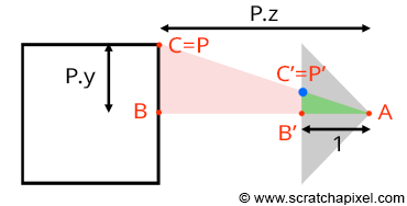
Let's look at our setup from the side and trace a line from one of the corners to the origin (the viewpoint). We can define two triangles: ABC and AB'C'. As you can see, these two triangles share the same origin (A). They are also, in a way, copies of each other, in that the angle formed by the edges AB and AC is the same as the angle formed by the edges AB' and AC'. Such triangles are referred to as similar triangles in mathematics. Similar triangles have an intriguing property: the ratio between their adjacent and opposite sides is identical. In other words:
$$ \frac{BC}{AB} = \frac{B'C'}{AB'}. $$Because the canvas is located 1 unit away from the origin, we know that AB' equals 1. We also know the position of B and C, which are the corner's z (depth) and y coordinates (height), respectively. Substituting these values into the equation above, we get:
$$ \frac{P.y}{P.z} = \frac{P'.y}{1}. $$Where P'.y is the y-coordinate of the point where the line going from the corner to the viewpoint intersects the canvas, which is, as mentioned earlier, the point from which we can draw an image of the box on the canvas. Thus:
$$ P'.y = \frac{P.y}{P.z}. $$As we can see, the projection of the corner's y-coordinate on the canvas is simply the corner's y-coordinate divided by its depth (the z-coordinate). This relation is one of the most fundamental in computer graphics, known as the z or perspective divide. The same principle applies to the x-coordinate. The projected point's x-coordinate (x') is the corner's x-coordinate divided by its z-coordinate.
However, because the z-coordinate of P is negative in our example (we will explain why this is always the case in the lesson from the Foundations of 3D Rendering section dedicated to the perspective projection matrix), when the x-coordinate is positive, the projected point's x-coordinate will become negative (similarly, if P.x is negative, P'.x will become positive. The same situation occurs with the y-coordinate). As a result, the image of the 3D object is mirrored both vertically and horizontally, which is not the effect we desire. Thus, to circumvent this issue, we will divide the P.x and P.y coordinates by -P.z instead, maintaining the sign of the x and y coordinates. We finally get:
$$ \begin{array}{l} P'.x = \frac{P.x}{-P.z} \\ P'.y = \frac{P.y}{-P.z}. \end{array} $$We now have a method to compute the actual positions of the corners as they appear on the surface of the canvas, i.e., the two-dimensional coordinates of the points projected onto the canvas. Let's update our basic program to compute these coordinates:
typedef float Point[3];
int main()
{
    Point corners[8] = {
         { 1, -1, -5},
         { 1, -1, -3},
         { 1,  1, -5},
         { 1,  1, -3},
         {-1, -1, -5},
         {-1, -1, -3},
         {-1,  1, -5},
         {-1,  1, -3}
    };

    for (int i = 0; i < 8; ++i) {
        // Divide the x and y coordinates by the z coordinate to
        // project the point onto the canvas
        float x_proj = corners[i][0] / -corners[i][2];
        float y_proj = corners[i][1] / -corners[i][2];
        printf("Projected corner %d: x:%f, y:%f\n", i, x_proj, y_proj);
    }

    return 0;
}

The size of the canvas itself is also arbitrary. It can be either a square or a rectangle. In our example, we made it two units wide in both dimensions, which means that the x and y coordinates of any points lying on the canvas fall within the range of -1 to 1 (Figure 9).
Question: What happens if any of the projected point coordinates is not within this range, for instance, if x' equals -1.1?
The point is not visible; it lies outside the boundary of the canvas.
At this point, we say that the projected point coordinates are in screen space (the space of the screen, where screen and canvas in this context are synonymous). But they are not straightforward to manipulate because they can be either negative or positive, and we need to understand what they refer to with respect to, for example, the dimensions of your computer screen (if we want to display these dots on the screen). For this reason, we will first normalize them, meaning we convert them from whatever range they were initially in to the range [0,1]. In our case, because we need to map the coordinates from -1 to 1 into 0 to 1, we can write:
float x_proj_remap = (1 + x_proj) / 2;
float y_proj_remap = (1 + y_proj) / 2;
The coordinates of the projected points are now in the range of 0 to 1. Such coordinates are said to be defined in NDC space, which stands for Normalized Device Coordinates. This is convenient because, regardless of the original size of the canvas (or screen), which can vary depending on the settings you used, we now have all points' coordinates defined in a common space. The term normalize is ubiquitous; it refers to remapping values from whatever range they were initially into the range [0,1]. Finally, we generally define point coordinates with regard to the dimensions of the final image, which, as you may know, is defined in terms of pixels. A digital image is nothing more than a two-dimensional array of pixels (as is your computer screen).
A 512x512 image is a digital image having 512 rows of 512 pixels each; or if you prefer, 512 columns of 512 vertically aligned pixels. Since our coordinates are already normalized, all we need to do to express them in terms of pixels is to multiply these NDC coordinates by the image dimension (512). Here, our canvas being square, we will also use a square image:
#include <cstdlib>
#include <cstdio>

typedef float Point[3];

int main()
{
    Point corners[8] = {
         { 1, -1, -5},
         { 1, -1, -3},
         { 1,  1, -5},
         { 1,  1, -3},
         {-1, -1, -5},
         {-1, -1, -3},
         {-1,  1, -5},
         {-1,  1, -3}
    };

    const unsigned int image_width = 512, image_height = 512;

    for (int i = 0; i < 8; ++i) {
        // Divide the x and y coordinates by the z coordinate to
        // project the point onto the canvas
        float x_proj = corners[i][0] / -corners[i][2];
        float y_proj = corners[i][1] / -corners[i][2];
        float x_proj_remap = (1 + x_proj) / 2;
        float y_proj_remap = (1 + y_proj) / 2;
        float x_proj_pix = x_proj_remap * image_width;
        float y_proj_pix = y_proj_remap * image_height;
        printf("Corner: %d x:%f y:%f\n", i, x_proj_pix, y_proj_pix);
    }

    return 0;
}
The resulting coordinates are said to be in raster space. "Raster" refers to the image itself as we know it—that is, a 2D grid of pixels. This grid can be viewed as a coordinate system with the origin of that coordinate system located in the top-left corner of the image, bearing coordinates (0,0). Conversely, the bottom-right corner of the image would have coordinates (width, height), where the unit of measurement is the pixel. Our program is still limited because it doesn't create an actual image of the box, but if you compile and run it with the following commands (copy/paste the code into a file and save it as box.cpp):
c++ box.cpp -o box
./box
You'll get:
Corner: 0 x:307.200012 y:204.800003
Corner: 1 x:341.333344 y:170.666656
Corner: 2 x:307.200012 y:307.200012
Corner: 3 x:341.333344 y:341.333344
Corner: 4 x:204.800003 y:204.800003
Corner: 5 x:170.666656 y:170.666656
Corner: 6 x:204.800003 y:307.200012
Corner: 7 x:170.666656 y:341.333344
You can use a paint program to create an image (set its size to 512x512) and add dots at the pixel coordinates you computed with the program. Then connect the dots to form the edges of the box, and you will obtain an actual image of the box (as shown in the video below). Pixel coordinates are integers, so you will need to round off the numbers provided by the program.
What Have We Learned?
-
We first need to describe three-dimensional objects using elements such as vertices and topology (information about how these vertices are connected to form polygons or faces) before we can produce an image of the 3D scene (a scene is a collection of objects).
-
Rendering is the process through which an image of a 3D scene is created. Regardless of the technique you use to create 3D models (and there are quite a few), rendering is a necessary step to 'see' any 3D virtual world.
-
From this simple exercise, it becomes apparent that mathematics (more so than programming) is crucial in creating an image with a computer. A computer is merely a tool to expedite computation, but the principles used to create this image are rooted in pure mathematics. Geometry plays an essential role in this process, especially for handling objects' transformations (scale, rotation, translation) and providing solutions to problems such as calculating angles between lines or determining the intersection between a line and other simple shapes (a plane, a sphere, etc.).
-
In conclusion, computer graphics is predominantly about applying mathematics in a computer program designed to generate an image (photo-real or not) as quickly as possible (and with the precision that computers are capable of).
-
Modeling encompasses all techniques used to create 3D models. Modeling techniques will be discussed in the Geometry/Modeling section.
-
While static models are sufficient for some applications, it is also possible to animate them over time. This means that an image of the model at each time step needs to be rendered (you can translate, rotate, or scale the box slightly between each consecutive image by animating the corners' coordinates or applying a transformation matrix to the model). More advanced animation techniques can simulate the deformation of the skin by bones and muscles. However, all these techniques share the characteristic that geometry (the faces making up the models) is deformed over time. Therefore, as the introduction suggests, time is also a crucial factor in CGI. Check the Animation section to learn more about this topic.
-
One particular field overlaps both animation and modeling. It includes all techniques used to simulate the motion of objects in a realistic manner. A vast area of computer graphics is devoted to simulating the motion of fluids (water, fire, smoke), fabric, hair, etc. The laws of physics are applied to 3D models to make them move, deform, or break as they would in the real world. Physics simulations are generally computationally intensive, but they can also run in real-time (depending on the complexity of the scene you simulate).
-
Rendering is also a computationally intensive task. The complexity depends on the amount of geometry in your scene and how photo-real you want the final image to be. In rendering, we differentiate between two modes, offline and real-time rendering. Real-time rendering is used (it's a requirement) for video games, where the content of the 3D scenes needs to be rendered at least 30 frames per second (60 frames a second is generally considered standard). The GPU is a processor specially designed to render 3D scenes as quickly as possible. Offline rendering is commonly used in CGI production for films where real-time is not required (images are precomputed and stored before being displayed at 24, 30, or 60 fps). It may take a few seconds to hours before a single image is complete. However, it can handle far more geometry and produces higher-quality images than real-time rendering. Nonetheless, the lines between real-time or offline rendering are increasingly blurring, with video games pushing the amount of geometry they can handle and the quality, and offline rendering engines striving to leverage the latest advancements in CPU technology to significantly enhance their performance.
Indeed, we/you learned a lot!
Where Should I Start?
We hope the simple box example has piqued your interest, but the primary goal of this introduction is to highlight the significance of geometry in computer graphics. Indeed, it's not solely about geometry, but a multitude of problems within the field can be effectively solved using geometric principles. Most computer graphics textbooks begin with a chapter on geometry, which can be somewhat daunting as it requires a substantial amount of study before one can start creating engaging content. Nonetheless, we suggest you first delve into the lesson on Geometry. There, we will discuss and learn about points, vectors, and normals. We'll explore coordinate systems and, more critically, matrices. Matrices are crucial for managing rotation, scaling, and/or translation; in essence, for handling transformations. These concepts recur throughout all computer graphics literature, making it imperative to grasp them early on.
Many (if not most) CG books offer an underwhelming introduction to geometry, possibly because the authors presume the reader has pre-existing knowledge or that specialized books on the subject are preferable. Our geometry lesson stands apart. It is comprehensive, immediately applicable to your daily work, and elucidates complex ideas in simple terms. We strongly encourage you to commence your foray into computer graphics programming by engaging with this lesson first.
What Should I Read Next?
Starting your journey in computer graphics programming with rendering tends to be both more accessible and enjoyable. The beginners' section was crafted specifically for individuals who are new to computer graphics programming. Therefore, if your ambition is to advance further, continue reading the lessons in this section in chronological order.