A Minimal Ray-Tracer: Rendering Spheres
Reading time: 11 mins.A Minimal Ray-Tracer: Rendering Spheres
In this chapter, we detail the program's source code provided with this lesson. The program is a basic yet functional tool that accurately renders a scene containing only spheres. Below is a list of the program's main features:
-
Camera transformations are supported, meaning we can render the scene from any viewpoint. This capability utilizes what we learned in the previous lesson on generating camera rays.
-
Correct geometry visibility. If a ray intersects more than one sphere, the sphere with the closest intersection distance is displayed.
-
Upon finding an intersection, both the normal and the texture coordinates at the intersected point on the sphere are calculated and used to shade the spheres.
One initial challenge is supporting different geometry types within the program. For instance, in this program version, we aim to render solely spheres. However, what if we wish to render a polygon mesh in the next version? There are several approaches to this problem, often resolved in C++ by leveraging the class inheritance mechanism. Typically, we first define a base class, offering a generic definition of geometry within the program. Then, we can add as many virtual functions as needed (derived classes can override virtual functions in C++) and tailor these methods for each class derived from the base class. For example:
class Object
{
public:
    // The virtual intersect function needs to be overridden by the derived class
    virtual bool intersect(const Vec3f &orig, const Vec3f &dir, float &t) const = 0;
    virtual ~Object() {} // Virtual destructor
    Object() {} // Constructor
};

class Sphere : public Object
{
public:
    ...
    bool intersect(const Vec3f &orig, const Vec3f &dir, float &t) const override
    {
        // Code to compute the intersection of the ray with a sphere
        ...

        return false;
    }
};

int main(...)
{
    Sphere mySphere;
    ...
    if (mySphere.intersect(orig, dir, t)) {
        // This ray intersects this instance of the class Sphere
    }
}
In the pseudo-code above, the class Object is purely virtual, meaning a class derived from Object must implement the intersect() method. This method is where you add the ray-geometry intersection code specific to the geometry type represented by the class, such as the ray-sphere intersection code we discussed in the second chapter of this lesson.
class Sphere : public Object
{
public:
    ...
    bool intersect(const Vec3f &orig, const Vec3f &dir, float &t) const override
    {
        float t0, t1; // Solutions for t if the ray intersects
#if 0
        // Geometric solution
        Vec3f L = center - orig;
        float tca = L.dotProduct(dir);
        if (tca < 0) return false;
        float d2 = L.dotProduct(L) - tca * tca;
        if (d2 > radius * radius) return false;
        float thc = sqrt(radius * radius - d2);
        t0 = tca - thc;
        t1 = tca + thc;
#else
        // Analytic solution
        Vec3f L = orig - center;
        float a = dir.dotProduct(dir);
        float b = 2 * dir.dotProduct(L);
        float c = L.dotProduct(L) - radius * radius;
        if (!solveQuadratic(a, b, c, t0, t1)) return false;
#endif
        if (t0 > t1) std::swap(t0, t1);

        if (t0 < 0) {
            t0 = t1; // If t0 is negative, let's use t1 instead
            if (t0 < 0) return false; // Both t0 and t1 are negative
        }

        t = t0;

        return true;
    }
    ...
};
Next time we decide to incorporate another geometry type, all we need to do is create a new class derived from Object and implement the necessary code to calculate the ray's intersection with this new geometry within the intersect() method. For instance:
class TriangulatedMesh : public Object
{
public:
    ...
    bool intersect(const Vec3f &orig, const Vec3f &dir, float &t) const override
    {
        // Code to compute the intersection of a ray with a triangulated mesh
        ...
        return true;
    }
    ...
};
For simplicity, we haven't introduced a Ray class in this program. This decision is made to demonstrate that creating a class solely to group two variables might not be justified. Consequently, we directly utilize the ray's origin and direction in the intersect() method.
Having established how to define a sphere, we can now create a scene populated with numerous spheres, with their positions and radii in 3D space randomly generated. These spheres are added to a list of objects. This list can accommodate any object of the type Object, but thanks to C++'s inheritance mechanism, any instance of a class derived from Object can also be included (notably, creating an instance of the purely virtual Object class is impossible). In our scenario, these would be instances of the Sphere class.
int main(int argc, char **argv)
{
    // Creating the scene (adding objects and lights)
    std::vector<std::unique_ptr<Object>> objects;

    // Generate a scene made of random spheres
    uint32_t numSpheres = 32;
    gen.seed(0);
    for (uint32_t i = 0; i < numSpheres; ++i) {
        Vec3f randPos((0.5 - dis(gen)) * 10, (0.5 - dis(gen)) * 10, (0.5 + dis(gen)) * 10);
        float randRadius = (0.5 + dis(gen)) * 0.5;
        objects.push_back(std::make_unique<Sphere>(randPos, randRadius));
    }

    // Setting up options
    Options options;
    options.width = 640;
    options.height = 480;
    options.fov = 51.52;
    options.cameraToWorld = Matrix44f(0.945519, 0, -0.325569, 0, -0.179534, 0.834209, -0.521403, 0, 0.271593, 0.551447, 0.78876, 0, 4.208271, 8.374532, 17.932925, 1);

    // Finally, render
    render(options, objects);

    return 0;
}
Moreover, we configure options like the image width and height in the program's main() function, then forward the object list and options to the render() function. Typically, the render() function iterates over all image pixels, constructing primary rays. The camera-to-world matrix is employed to transform the rays' origin and direction.
void render(
    const Options &options,
    const std::vector<std::unique_ptr<Object>> &objects)
{
    ...
    float scale = std::tan(deg2rad(options.fov * 0.5));
    float imageAspectRatio = options.width / static_cast<float>(options.height);
    Vec3f orig;
    options.cameraToWorld.multVecMatrix(Vec3f(0), orig);
    for (uint32_t j = 0; j < options.height; ++j) {
        for (uint32_t i = 0; i < options.width; ++i) {
#ifdef MAYA_STYLE
            float x = (2 * (i + 0.5) / static_cast<float>(options.width) - 1) * scale;
            float y = (1 - 2 * (j + 0.5) / static_cast<float>(options.height)) * scale * 1 / imageAspectRatio;
#else
            float x = (2 * (i + 0.5) / static_cast<float>(options.width) - 1) * imageAspectRatio * scale;
            float y = (1 - 2 * (j + 0.5) / static_cast<float>(options.height)) * scale;
#endif
            Vec3f dir;
            options.cameraToWorld.multDirMatrix(Vec3f(x, y, -1), dir);
            dir.Normalize();
            *(pix++) = castRay(orig, dir, objects);
        }
    }

    // Save the result to a PPM image (keep these flags if you compile under Windows)
    ...
}
Regarding the MAYA_STYLE if-else statement: when the image isn't square, we need to adjust the screen window by the image aspect ratio. Mathematically, this adjustment can be achieved in two ways. First, you can multiply the screen window's width (x-axis) by the image aspect ratio. For example, if the image resolution is 640x480, this gives us an aspect ratio of 1.33, making the screen window 1.33 units wide in the x-direction and 1 unit tall in the y-direction (assuming the field of view doesn't affect the screen window size here). Alternatively, we could maintain the screen window's width at 1 unit along the x-axis and scale it along the y-axis by dividing by the inverse of the image aspect ratio, as illustrated below.
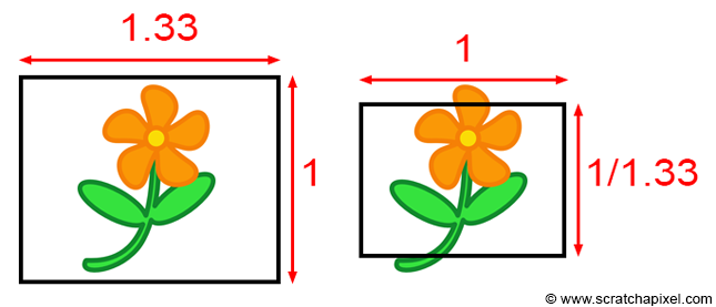
Both approaches mathematically alter the object's framing seen through the camera but are equally valid. Maya adopts the second approach. Thus, if you aim for your ray tracer's output to align with a Maya render, you will need to adjust the ray's direction along the y-axis by the inverse of the image aspect ratio. Otherwise, you can leave the y-coordinates of the ray unchanged and scale the x-coordinate by the aspect ratio:
#ifdef MAYA_STYLE
float x = (2 * (i + 0.5) / (float)options.width - 1) * scale;
float y = (1 - 2 * (j + 0.5) / (float)options.height) * scale / imageAspectRatio;
#else
float x = (2 * (i + 0.5) / (float)options.width - 1) * imageAspectRatio * scale;
float y = (1 - 2 * (j + 0.5) / (float)options.height) * scale;
#endif
Activate the first case by adding the option -DMAYA_STYLE to your compilation command.
The ray origin, direction, and object list are passed to the castRay() function. Rather than iterating over all the scene objects within this function, we defer to the trace() function. The trace() function, receiving the object list alongside the ray origin and direction, loops through the scene's objects, invoking each object's intersect() method. Consequently, if the object is a sphere, it triggers the Sphere class's intersect() method. For a TriangulatedMesh (pending implementation), it would call the TriangulateMesh class's intersect() method. This function signifies an intersection with the object as true and otherwise as false. Upon finding an intersection, \(t\), which is input to the intersect() method, gets updated with the distance from the ray's origin to the intersected point. The trace() function is pivotal for maintaining the closest intersection distance, as a ray might intersect multiple objects. The variable tNear is initially set to a significantly high number and is updated upon discovering a closer intersection (as demonstrated in the pseudocode below).
bool trace(
    const Vec3f &orig, const Vec3f &dir,
    const std::vector<std::unique_ptr<Object>> &objects,
    float &tNear, const Object *&hitObject)
{
    tNear = kInfinity;
    auto iter = objects.begin();
    for (; iter != objects.end(); ++iter) {
        float t = kInfinity;
        if ((*iter)->intersect(orig, dir, t) && t < tNear) {
            hitObject = iter->get();
            tNear = t;
        }
    }

    return (hitObject != nullptr);
}
Regarding std::unique_ptr: unique_ptr is a type of smart pointer that maintains exclusive ownership of an object through a pointer and deallocates that object when the unique_ptr goes out of scope. Employing unique_ptr for dynamically allocated geometry management absolves the programmer of manually freeing memory, as the smart pointer automatically handles this upon scope exit.
If the trace() function returns true in the castRay() function, it indicates that the ray intersects with the object identified by the hitObject variable. We also determine the intersection distance t to that object. From this information, we can calculate the intersection point (line 9 below) and invoke the getSurfaceData() method on the intersected object to obtain the normal and texture coordinates of the surface at the intersection point (line 12 below). The normal and texture coordinates are then utilized to shade the point. By inverting the direction of the ray and using it in a dot product with the normal, we can calculate what is known as a facing ratio. This ratio approaches 1 when the normal and the ray direction align, and approaches or drops below 0 when they are perpendicular or facing opposite directions. Finally, the texture coordinates are used to compute a checkerboard pattern. The color at the intersection point is a blend of the object's color (randomly assigned upon creation), the facing ratio result, and the pattern:
Vec3f castRay(
    const Vec3f &orig, const Vec3f &dir,
    const std::vector<std::unique_ptr<Object>> &objects)
{
    Vec3f hitColor = 0;
    const Object *hitObject = nullptr; // This is a pointer to the hit object.
    float t; // This is the intersection distance from the ray origin to the hit point.
    if (trace(orig, dir, objects, t, hitObject)) {
        Vec3f Phit = orig + dir * t;
        Vec3f Nhit;
        Vec2f tex;
        hitObject->getSurfaceData(Phit, Nhit, tex);
        // Use the normal and texture coordinates to shade the hit point.
        // The normal is used to calculate a simple facing ratio, and the texture coordinate
        // to compute a basic checkerboard pattern.
        float scale = 4;
        float pattern = (fmodf(tex.x * scale, 1) > 0.5) ^ (fmodf(tex.y * scale, 1) > 0.5);
        hitColor = std::max(0.f, Nhit.dotProduct(-dir)) * mix(hitObject->color, hitObject->color * 0.8, pattern);
    }

    return hitColor;
}
This section wraps up the explanation of the program's source code. The outcome of the program is illustrated in the image below. On the left is a rendering of the scene in Maya, and on the right is the output generated by our program. The only distinction is the color of the objects, which we did not attempt to precisely replicate in the Maya scene. As observable, the spheres occupy identical positions in both images, and the patterns match as well.
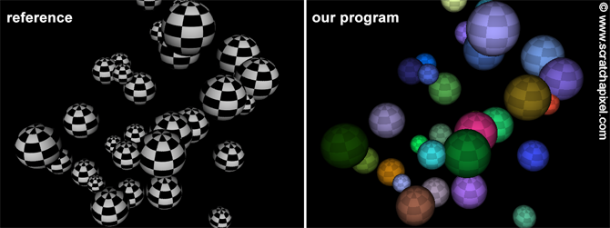
As always, the complete source code is available on GitHub.