From Polygon to Triangle Mesh
Reading time: 12 mins.Introduction
In the previous lesson, we learned how to render triangles, leading us to the next step: rendering more complex objects. Usually, the simplest form of object we can find right after simple primitives, such as spheres and triangles, are polygonal objects (which are also called polygon meshes).
Polygon meshes are not used much in films (where a more sophisticated type of primitive, the subdivision surface, is preferred). Still, they stay trendy in video games and real-time applications in general. These objects are made out of polygons which we also call faces. A polygon or a face is a flat surface (it should be, but if the vertices making up the face are not coplanar, it won't be) defined by a set of vertices connected to form a closed shape — two vertices connected form an edge. Therefore, the number of vertices making up a face has to be greater or equal to three. Three vertices define a triangle, and four define a quad. We can also combine polygons to create complex polyhedral objects.
Polygon meshes are simple in principle but have their own set of problems: how do we smooth a low poly mesh (a mesh that has a small number of polygons may appear blocky), or how do we efficiently encode the vertex connectivity data of a mesh? These techniques will be studied in the advanced section. This introductory lesson aims to learn how to define a polygon mesh in our program (chapter 2) and render this mesh using ray tracing (chapter 3).
Mesh Definition

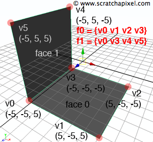
A polygon mesh is made of vertices connected to each other to form faces. The first thing we expect to define a mesh is a list of vertices. Let's consider an example of two quads sharing a common edge (figure 1). In this example, we would have 6 vertices v0, v1, v2, v3, v4, and v5. The other information we need is the mesh's total number of faces. In our example, this number is 2. We also need an array of integers that indicates how many vertices each face is made of (the face index array). The first and the second face from our mesh have 4 vertices; therefore, this array would contain the following data: [4 4]. This array's size equals the number of faces in the mesh (2). Finally, for each face, we need to know how the vertices are connected to other to create the faces, their indexes in the vertex array list, and the order in which they should be connected. The vertices v0, v1, v2, and v3 make up the first face while connecting v0, v3, v4, and v5 in this order gives the second face. We can store this information in an array of integer values whose size equals the sum of the number of vertices each face is made of. The mesh contains 2 faces which are each connected to 4 vertices. Therefore, this array should be of size 8 and have the following data: [0 1 2 3 0 3 4 5]. Here is what we would get in pseudocode:
// mesh vertices
Vec3f P[6] = {Vec3f (-5, -5,  5), Vec3f ( 5, -5,  5), Vec3f ( 5, -5, -5), Vec3f (-5, -5, -5), Vec3f (-5,  5, -5), Vec3f (-5,  5, 5)};
uint32_t npolys = 2;  //number of faces
uint32 faceIndex[2] = {4, 4};  //face index array
uint32 vertexIndex[8] = {0, 1, 2, 3, 0, 3, 4, 5};  //vertex index array
Remember that if the current orientation is left-handed, then a polygon whose vertices are specified in clockwise order (from the camera's point of view) will be a front-facing polygon (its normal vector points toward the camera). If the current orientation is right-handed, then polygons whose vertices were specified in counterclockwise order will be front-facing.
Names of the variables in the pseudocode follow the conventions defined in the RenderMan Interface Specification for the RiPointsPolygons method. The RenderMan Interface "is a standard interface between modeling programs and rendering programs capable of producing photorealistic quality images" proposed and maintained by Pixar. This document can easily be found on the web, and reading it is recommended as it contains a great deal of very interesting and helpful information (even though Pixar doesn't maintain it anymore).
class PolygonMesh : public Object
{
public:
   PolygonMesh(uint32_t nfaces, int *fi, int *vi, Vec3f *p) :
        numFaces(nf), faceIndex(NULL), vertexIndex(NULL), P(NULL)
   {
       // compute vertArraySize and maxVertexIndex
       uint32_t vertArraySize = 0;
       uint32_t maxVertexIndex = 0, index = 0;
       for (uint32_t i = 0; i < numFaces; ++i) {
           vertArraySize += nv[i];
           for (uint32_t j = 0; j < fi[i]; ++j)
               if (vi[index + j] > maxVertexIndex)
                   maxVertexIndex = vi[index + j];
           index += fi[i];
       }
       maxVertexIndex += 1;
       pts = std::unique_ptr<Vec3f []>(new point[maxVertexIndex]);
       for (uint32_t i = 0; i < maxVertexIndex; ++i) P[i] = p[i];
       vertexIndex = std::unique_ptr<uint32_t []>(new int[maxVertexIndex]);
       for (uint32_t i = 0; i < maxVertexIndex; ++i) vertexIndex [i] = vi[i];
       faceIndex = std::unique_ptr<uint32_t>(new int[numFaces]);
       for (uint32_t i = 0; i < numFaces; ++i) faceIndex[i] = fi[i];
   };
   ~PolygonMesh() { /* release memory */ ... }
   bool intersect(...) const { ... }
   void getSurfaceData(...) const { ... }
   uint32_t numFaces;  //number of faces
   std::unique_ptr<uint32_t []> faceIndex;  //face index
   std::unique_ptr<uint32_t []> vertexIndex;  //vertex index
   std::unique_ptr<Vec3f []> P;
};

int main(...)
{
   ...
   uint32_t numFaces = 2;
   uint32_t faceIndex[2] = {4, 4};
   uint32_t vertexIndex[8] = {0, 1, 2, 3, 0, 3, 4, 5};
   Vec3f P[6] = {
       Vec3f (-5, -5,  5), Vec3f ( 5, -5,  5),
       Vec3f ( 5, -5, -5), Vec3f (-5, -5, -5),
       Vec3f (-5,  5, -5), Vec3f (-5,  5,  5),
   };
   PolygonMesh *mesh = new PolygonMesh(numFaces, faceIndex, vertexIndex, P);
   ...
}
The code is quite simple (a functional C++ version of this code is available in the last chapter of this lesson). The point list, face, vertex index array, and the number of faces are passed to the MeshPolygon constructor class. However, we need to find out how many points are in the point array. To find out, we look for the vertex with the maximum index value in the vertex index array (lines 13-14). The first element of an array in C++ start at 0; therefore, the total number of vertices in the point list is the maximum index value plus 1 (line 17).
As you can see in the code above, we added the two methods,s intersect() and getSurfaceData(), but left them empty. We will fill them in the next chapter.
Convert Polygons to Triangles

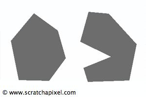
Unfortunately, it is not easy to directly ray-trace a polygon mesh. For simplicity and generality, it is usually better to convert the polygon mesh into a triangle mesh and ray-trace each triangle rather than develop an algorithm to trace polygons. This partially explains why we put so much effort into ray-tracing triangles efficiently (as described in the previous lesson). It is much easier to have one efficient, highly optimized ray-primitive intersection and convert every type of geometry to this primitive rather than implementing an efficient ray-geometry intersection routine every time a new kind of geometry is added to the system. In addition, converting polygons to triangles is simple. However, our technique will only work for convex polygons. Concave polygons require a different method which we won't look at in this lesson. The technique we will use for this lesson is simple to understand and implement, but other methods can produce a better result (there is a lot of research on meshing). As we already mentioned, it only works for convex polygons. If you are still determining whether or not your mesh contains concave polygons, the best is to triangulate it first in a program such as Maya before exporting it to the renderer.

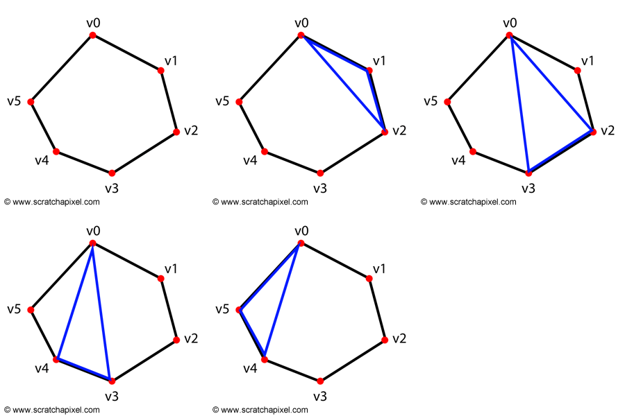
Triangulating a convex polygon is very simple. We take the first vertex in the face and draw triangles by connecting the vertices v[0], v[n + 1], and v[n + 2] to create a triangle, where \(n\) is the current number of triangles formed minus one. When \(n = 0\), the first triangle is formed by the vertices v[0] v[1] and v[2], when \(n = 1\) the second triangle is formed by the vertices v[0], v[2] and v[3], and for \(n = 2\), the third triangle is formed by v[0], v[3], v[4], and so on. Figure 3 illustrates this process. The number of triangles created for a polygon is always equal to the number of vertices in the polygon minus two (create some polygons yourself to verify this observation).
numTrisInFace = numVertsInFace - 2;
Our program will need to triangulate the original mesh before it gets rendered, so we don't want to store the original face and vertex index arrays. We will create new ones from the data passed to the mesh constructor class. We first want to compute how many triangles the original mesh will generate (which we can easily do since we know that each face containing \(N\) vertices results in \(N - 2\) triangles). We also know that each face of a triangulated mesh has three vertices; therefore, we don't need to store the face index array for triangulated mesh. However, we will need to regenerate a vertex index array to store which vertices each triangle in the mesh is connected to. This array's size equals the number of triangles multiplied by 3. The pseudocode should make this process easier to understand:
TriangleMesh(
    const uint32_t nfaces,
    const std::unique_ptr<uint32_t []> &faceIndex,
    const std::unique_ptr<uint32_t []> &vertsIndex,
    const std::unique_ptr<Vec3f []> &verts,
    const std::unique_ptr<Vec3f []> &normals = nullptr,
    const std::unique_ptr<Vec2f []> &st = nullptr) :
    numTris(0)
{
    uint32_t k = 0, maxVertIndex = 0;
    // find out how many triangles we need to create for this mesh
    for (uint32_t i = 0; i < nfaces; ++i) {
        numTris += faceIndex[i] - 2;
        for (uint32_t j = 0; j < faceIndex[i]; ++j)
            if (vertsIndex[k + j] > maxVertIndex)
                maxVertIndex = vertsIndex[k + j];
        k += faceIndex[i];
    }
    maxVertIndex += 1;

    // allocate memory to store the position of the mesh vertices
    P = std::unique_ptr<Vec3f []>(new Vec3f[maxVertIndex]);
    for (uint32_t i = 0; i < maxVertIndex; ++i) {
        P[i] = verts[i];
    }

    // allocate memory to store triangle indices
    trisIndex = std::unique_ptr<uint32_t []>(new uint32_t [numTris * 3]);
    uint32_t l = 0;
    // generate the triangle index array
    for (uint32_t i = 0, k = 0; i < nfaces; ++i) {  //for each  face
        for (uint32_t j = 0; j < faceIndex[i] - 2; ++j) {  //for each triangle in the face
            trisIndex[l] = vertsIndex[k];
            trisIndex[l + 1] = vertsIndex[k + j + 1];
            trisIndex[l + 2] = vertsIndex[k + j + 2];
            l += 3;
        }
        k += faceIndex[i];
    }
    // store normals and st coordinates
    ...
}
The computation of the triangle vertex indexes is straightforward. We create an array whose size equals the number of triangles multiplied by 3 (since each triangle requires three indexes into the point array - line xx). We loop over each face, then over each triangle in this face, and compute the indexes for the current triangle from the input vertex index array, which we store in the triangle vertex index array (line xx to xx). At this stage, we have a renderable polygon mesh in the form of a triangulated polygon mesh.
Normals

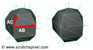
The normal of a triangle can be computed from the cross product of vectors AB and AC (figure 4). This normal is called a face normal because it corresponds to a vector perpendicular to the plane defined by the triangle's three vertices. Therefore the normal vector is also perpendicular to the face (or triangle in that case. Remember that polygons should be coplanar) hence the term face normal. However, we can also compute what is called a vertex normal, which, as its name suggests, is a normal defined at the position of each vertex in the mesh. This normal is useful for smooth shading (as shown in figure 4). It is usually calculated from an average of all the face normals the vertex is connected to (you sum the normals and divide by the number of vertices making up the face). Vertex normals are required for shading, and they are usually computed by the modeling program and passed on to the renderer as part of the mesh description. When they are not defined, the renderer needs to calculate them itself. Computing vertex normals will be addressed in a future lesson. For now, we will assume that they are always defined in the object geometry file.
Texture Coordinates
Unless the geometry is generated on the fly in the program, st coordinates are generally generated in the modeling program and exported to the file in which the object is stored. Similarly to normals, we will expect texture coordinates to be defined in the object geometry file.
What's Next?
In this chapter, we have explained what information we need to store and compute polygon meshes. The next chapter will explain how these meshes can be ray-traced and provide a practical C++ example.