The Visibility Problem, the Depth Buffer Algorithm and Depth Interpolation
Reading time: 15 mins.In the second chapter of this lesson, we learned that the third coordinate of the projected point (the point in screen space) stores the original vertex's z-coordinate (the z-coordinate of the point in camera space):
$$ \begin{array}{l} P_{\text{screen}}.x = \dfrac{ \text{near} \cdot P_{\text{camera}}.x }{ -P_{\text{camera}}.z}\\ P_{\text{screen}}.y = \dfrac{ \text{near} \cdot P_{\text{camera}}.y }{ -P_{\text{camera}}.z}\\ P_{\text{screen}}.z = -P_{\text{camera}}.z\\ \end{array} $$Finding the z-coordinate of a point on the surface of the triangle is useful when a pixel overlaps more than one triangle. The method to determine this z-coordinate involves interpolating the original vertices' z-coordinates using the barycentric coordinates we discussed in the previous chapter. In essence, we can treat the z-coordinates of the triangle vertices as any other vertex attribute and interpolate them in the same manner as we interpolated colors in the previous chapter. Before delving into the details of how this z-coordinate is computed, let's begin by explaining why it is necessary to do so.
The Depth-Buffer or Z-Buffer Algorithm and Hidden Surface Removal
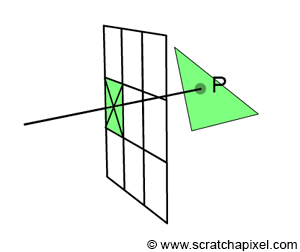
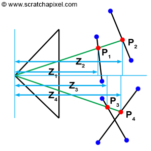
When a pixel overlaps a point, what we observe through that pixel is a small area on the surface of a triangle, which for simplification, we will reduce to a single point (denoted as P in Figure 1). Thus, each pixel covering a triangle corresponds to a point on the surface of that triangle. Of course, if a pixel covers more than one triangle, we then have several of these points. The challenge arises when this happens, as we need to determine which one of these points is visible. We have illustrated this concept in 2D in Figure 2. We could test triangles from back to front (this technique would require sorting triangles by decreasing depth first), but this doesn't always work when triangles intersect each other (Figure 2, bottom). The only reliable solution is to compute the depth of each triangle a pixel overlaps and then compare these depth values to find out which one is closest to the camera. If you look at Figure 2, you can see that a pixel in the image overlaps two triangles at P1 and P2. However, the z-coordinate at P1 (Z1) is lower than the z-coordinate at P2 (Z2), thus we can deduce that P1 is in front of P2. Note that this technique is necessary because triangles are tested in a "random" order. As mentioned before, we could sort out triangles in decreasing depth order, but this is not sufficient. Generally, they are just tested in the order they are specified in the program, and for this reason, a triangle T1 that is closer to the camera can be tested before a triangle T2 that is further away. If we were not comparing these triangles' depths, then we would end up, in this case, seeing the triangle which was tested last (T2) when in fact, we should be seeing T1. As mentioned many times before, this is called the visibility problem or hidden surface problem. Algorithms for ordering objects so that they are drawn correctly are called visible surface algorithms or hidden surface removal algorithms. The depth-buffer or z-buffer algorithm that we are going to study next belongs to this category of algorithms.
One solution to the visibility problem is to use a depth-buffer or z-buffer. A depth-buffer is nothing more than a two-dimensional array of floats that has the same dimensions as the frame-buffer and is used to store the depth of the object as the triangles are being rasterized. When this array is created, we initialize each pixel in the array with a very large number. If we find that a pixel overlaps the current triangle, we proceed as follows:
-
We first compute the z-coordinate or depth of the point on the triangle that the pixel overlaps.
-
We then compare that current triangle's depth with the value stored in the depth buffer for that pixel.
-
If we find that the value stored in the depth-buffer is greater than the depth of the point on the triangle, then the new point is closer to the observer or the camera than the point stored in the depth buffer at that pixel location. The value stored in the depth-buffer is then replaced with the new depth, and the frame-buffer is updated with the current triangle color. On the other hand, if the value stored in the depth-buffer is smaller than the current depth sample, then the triangle that the pixel overlaps is hidden by the object whose depth is currently stored in the depth-buffer.
Note that once all triangles have been processed, the depth-buffer contains "some sort" of an image that represents the "distance" between the visible parts of the objects in the scene and the camera (this is not a distance but the z-coordinate of each point visible through the camera). The depth buffer is essentially useful to solve the visibility problem; however, it can also be used in post-processing to implement effects such as 2D depth of field, adding fog, etc. All these effects are better done in 3D, but applying them in 2D is often faster, though the result is not always as accurate as what you can achieve in 3D.
Here is an implementation of the depth-buffer algorithm in pseudo-code:
float *depthBuffer = new float[imageWidth * imageHeight];
// Initialize the depth-buffer with a very large number
for (uint32_t y = 0; y < imageHeight; ++y)
    for (uint32_t x = 0; x < imageWidth; ++x)
        depthBuffer[y * imageWidth + x] = INFINITY;

for (each triangle in the scene) {
    // Project triangle vertices
    ...
    // Compute the 2D triangle bounding-box
    ...
    for (uint32_t y = bbox.min.y; y <= bbox.max.y; ++y) {
        for (uint32_t x = bbox.min.x; x <= bbox.max.x; ++x) {
            if (pixelOverlapsTriangle(x + 0.5, y + 0.5)) {
                // Compute the z-coordinate of the point on the triangle surface
                float z = computeDepth(...);
                // The current point is closer than the object stored in the depth/frame-buffer
                if (z < depthBuffer[y * imageWidth + x]) {
                     // Update the depth-buffer with that depth
                     depthBuffer[y * imageWidth + x] = z;
                     frameBuffer[y * imageWidth + x] = triangleColor;
                }
            }
        }
    }
}
Finding Z by Interpolation

The principle of the depth-buffer is straightforward and easy to comprehend. Now, we need to explain how the depth values are computed. Let's reiterate what the depth value signifies. When a pixel overlaps a triangle, it covers a small surface on the triangle, which, for simplification, we will reduce to a single point (point P in Figure 1). Our goal is to determine this point's z-coordinate. As mentioned earlier in this chapter, if we are aware of the triangle vertices' z-coordinate (which we are, as they are stored in the projected point's z-coordinate), all we need to do is interpolate these coordinates using P's barycentric coordinates (Figure 4):
$$P.z = \lambda_0 \cdot V0.z + \lambda_1 \cdot V1.z + \lambda_2 \cdot V2.z.$$While this approach sounds technically feasible, it unfortunately does not work. Let's explore why. The issue is not with the formula itself, which is perfectly valid. The challenge arises once the vertices of a triangle are projected onto the canvas (after performing the perspective divide), then z, the value we wish to interpolate, no longer varies linearly across the surface of the 2D triangle. This concept is more easily demonstrated with a 2D example.
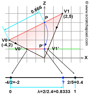
The secret is unveiled in Figure 4. Imagine we want to find the "image" of a line defined in 2D space by two vertices V0 and V1, with the canvas represented by the horizontal green line, located one unit away (along the z-axis) from the coordinate system origin. Tracing lines from V0 and V1 to the origin, we intersect the green lines at two points (denoted V0' and V1' in the figure), lying on the canvas one unit away from the origin. The x-coordinate of these points can be computed using perspective projection by dividing the original vertex x-coordinates by their z-coordinate:
$$ \begin{array}{l} V0'.x = \dfrac{V0.x}{V0.z} = \dfrac{-4}{2} = -2,\\ V1'.x = \dfrac{V1.x}{V1.z} = \dfrac{2}{5} = 0.4. \end{array} $$Our task is to determine the z-coordinate of P, a point on the line defined by V0 and V1, knowing only the position of its projection P' on the green line, with coordinates {0,1}. This scenario mirrors the challenge of finding the z-coordinate of a point on the triangle overlapped by a pixel. Here, P' represents the pixel, and P is the point on the triangle overlapped by the pixel. We now compute the "barycentric coordinate" of P' with respect to V0' and V1', denoted as \(\lambda\). Like the barycentric coordinates for our triangle, \(\lambda\) falls within the range [0,1]. To find \(\lambda\), we measure the distance between V0' and P' (along the x-axis) and divide this by the distance between V0' and V1'. If linear interpolation of the z-coordinates of the original vertices V0 and V1 using \(\lambda\) to find P's depth is accurate, we should obtain the value 4 (as visually deduced from the illustration, the coordinates of P are {0,4}). Let's first calculate \(\lambda\):
$$\lambda = \dfrac{P'x - V0'.x}{V1'.x - V0'.x} = \dfrac{0 - (-2)}{0.4 - (-2)}= \dfrac{2}{2.4} = 0.833.$$Linearly interpolating the z-coordinates of V0 and V1 to determine P's z-coordinate yields:
$$P.z = V0.z \cdot (1-\lambda) + V1.z \cdot \lambda = 2 \cdot (1 - 0.833) + 5 \cdot 0.833 = 4.5.$$This result is not as expected! Interpolating the original vertices' z-coordinates using P's "barycentric coordinates" or \(\lambda\) in this example, to find P's z-coordinate is flawed. Why? Simply put, perspective projection preserves lines but does not preserve distances. It is evident in Figure 4 that the ratio of the distance between V0 and P over the distance between V0 and V1 (0.666) does not match the ratio of the distance between V0' and P' over the distance between V0' and V1' (0.833). If \(\lambda\) equaled 0.666, the interpolation would be accurate, but the problem lies in \(\lambda\) being 0.833. So, how do we accurately find the z-coordinate of P?
The solution lies in computing the inverse of P's z-coordinate by interpolating the inverses of the vertices V0 and V1's z-coordinates using \(\lambda\). Specifically:
$$\dfrac{1}{P.z} = \color{purple}{\dfrac{1}{V0.z} \cdot (1-\lambda) + \dfrac{1}{V1.z} \cdot \lambda}.$$Verifying its effectiveness:
$$\dfrac{1}{P.z} = \dfrac{1}{2} \cdot (1 - \dfrac{2}{2.4}) + \dfrac{1}{5} \cdot (\dfrac{2}{2.4}) = 0.25.$$Taking the inverse of this result gives us P's z-coordinate value of 4, which is correct! As previously mentioned, the correct approach is to linearly interpolate the vertices' inverse z-coordinates using barycentric coordinates, and then invert the result to find P's depth (its z-coordinate). For our triangle, the formula becomes:
$$\dfrac{1}{P.z} = \dfrac{1}{V0.z} \cdot \lambda_0 + \dfrac{1}{V1.z} \cdot \lambda_1 + \dfrac{1}{V2.z} \cdot \lambda_2.$$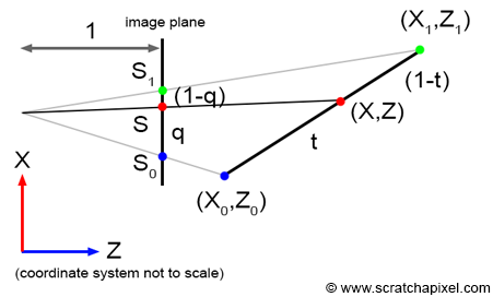
Let's examine this problem more formally. Why is it necessary to interpolate the inverse z-coordinates of a vertex? The explanation is somewhat intricate, and you may choose to skip it. Consider a line in camera space defined by two vertices with coordinates \((X_0,Z_0)\) and \((X_1,Z_1)\). The projection of these vertices onto the screen is denoted \(S_0\) and \(S_1\), respectively. In this example, we assume the distance between the camera origin and the canvas is 1, as illustrated in Figure 5. Let \(S\) represent a point on the line defined by \(S_0\) and \(S_1\), with a corresponding point \(P\) on the 2D line, whose coordinates are \((X,Z = 1)\) (assuming the screen or the projection line is 1 unit away from the coordinate system origin). The parameters \(t\) and \(q\) are defined as follows:
$$ \begin{aligned} P &= P_0 \cdot (1-t) + P_1 \cdot t,\\ S &= S_0 \cdot (1-q) + S_1 \cdot q.\\ \end{aligned} $$This can also be expressed as:
$$ \begin{aligned} P &= P_0 + t \cdot (P_1 - P_0),\\ S &= S_0 + q \cdot (S_1 - S_0).\\ \end{aligned} $$Thus, the \((X,Z)\) coordinates of point \(P\) can be determined by interpolation (Equation 1):
$$ (X,Z) = (X_0 + t \cdot (X_1 - X_0), Z_0 + t \cdot (Z_1 - Z_0)). $$Similarly (Equation 2):
$$ S = S_0 + q \cdot (S_1 - S_0). $$Since \(S\) is a 1D point (having been projected onto the screen), it lacks a z-coordinate. \(S\) can also be calculated as:
$$ S = \frac{X}{Z}. $$Therefore:
$$ Z = \frac{X}{S}. $$Substituting the numerator with Equation 1 and the denominator with Equation 2 yields (Equation 3):
$$ Z = \frac{X_0 + t \cdot (X_1 - X_0)}{S_0 + q \cdot (S_1 - S_0)} $$Also:
$$ \begin{aligned} S_0 &= \frac{X_0}{Z_0},\\ S_1 &= \frac{X_1}{Z_1}. \end{aligned} $$Hence (Equation 4):
$$ \begin{aligned} X_0 &= S_0 \cdot Z_0,\\ X_1 &= S_1 \cdot Z_1. \end{aligned} $$Substituting \(X_0\) and \(X_1\) in Equation 3 with the expressions from Equation 4 gives (Equation 5):
$$ Z = \frac{S_0 \cdot Z_0 + t \cdot (S_1 \cdot Z_1 - S_0 \cdot Z_0)}{S_0 + q \cdot (S_1 - S_0)} $$Recalling from Equation 1 (Equation 6):
$$ Z = Z_0 + t \cdot (Z_1 - Z_0). $$Combining Equations 5 and 6, we obtain:
$$ (Z_0 + t \cdot (Z_1 - Z_0)) \cdot (S_0 + q \cdot (S_1 - S_0)) = S_0 \cdot Z_0 + t \cdot (S_1 \cdot Z_1 - S_0 \cdot Z_0), $$Let's see how the equation can be simplified to express the parameter \(t\) in terms of \(q\). we proceed as follows:
1. Distribute and expand the terms on both sides:
$$ \begin{aligned} Z_0 \cdot S_0 + Z_0 \cdot q \cdot (S_1 - S_0) + t \cdot (Z_1 - Z_0) \cdot S_0 + t \cdot (Z_1 - Z_0) \cdot q \cdot (S_1 - S_0) &= S_0 \cdot Z_0 + t \cdot (S_1 \cdot Z_1 - S_0 \cdot Z_0), \end{aligned} $$2. Isolate the term involving \(t\) to one side to solve for \(t\):
$$ \begin{aligned} t \cdot [(Z_1 - Z_0) \cdot S_0 + (Z_1 - Z_0) \cdot q \cdot (S_1 - S_0) - (S_1 \cdot Z_1 - S_0 \cdot Z_0)] &= -q \cdot Z_0 \cdot (S_1 - S_0), \end{aligned} $$3. Further simplification yields:
$$ \begin{aligned} t \cdot [Z_1 \cdot S_0 - Z_0 \cdot S_0 + (Z_1 - Z_0) \cdot q \cdot (S_1 - S_0) - S_1 \cdot Z_1 + S_0 \cdot Z_0] &= -q \cdot Z_0 \cdot (S_1 - S_0), \end{aligned} $$4. Factorizing to simplify the terms involving \(t\):
$$ \begin{aligned} t \cdot (S_1 - S_0) \cdot [Z_1 - q \cdot (Z_1 - Z_0)] &= q \cdot Z_0 \cdot (S_1 - S_0), \end{aligned} $$5. Isolating \(t\), we obtain:
$$ \begin{aligned} t \cdot [q \cdot Z_0 + (1-q) \cdot Z_1] &= q \cdot Z_0, \end{aligned} $$6. Simplifying to find \(t\) in terms of \(q\):
$$ t = \frac{q \cdot Z_0}{q \cdot Z_0 + (1-q) \cdot Z_1}. $$This formulation demonstrates the relationship between the parameter \(t\), which is used to interpolate between two points in 3D space, and \(q\), which is used for the interpolation on the projected screen space.
Substituting for \(t\) in Equation 6 yields:
$$ \begin{aligned} Z &= Z_0 + t \cdot (Z_1 - Z_0) = Z_0 + \frac{q \cdot Z_0 \cdot (Z_1 - Z_0)}{q \cdot Z_0 + (1-q) \cdot Z_1},\\ &= \frac{Z_0 \cdot Z_1}{q \cdot Z_0 + (1-q) \cdot Z_1},\\ &= \frac{1}{\frac{q}{Z_1} + \frac{(1-q)}{Z_0}},\\ &= \frac{1}{\frac{1}{Z_0} + q \cdot (\frac{1}{Z_1} - \frac{1}{Z_0})}.\\ \end{aligned} $$Finally, we derive:
$$ \frac{1}{Z} = \frac{1}{Z_0} + q \cdot (\frac{1}{Z_1} - \frac{1}{Z_0}) = \frac{1}{Z_0} \cdot (1-q) + \frac{1}{Z_1} \cdot q. $$This formula concludes our exploration into why interpolating the inverse z-coordinates of a vertex is essential.
An alternative approach to explaining the depth interpolation issue involves considering the triangle (in 3D or camera space) lying on a plane. The plane equation is (Equation 1):
$$ AX + BY + CZ = D. $$Given that:
$$ \begin{aligned} X_{screen} &= \frac{X_{camera}}{Z_{camera}},\\ Y_{screen} &= \frac{Y_{camera}}{Z_{camera}}, \end{aligned} $$it follows that:
$$ \begin{aligned} X_{camera} &= X_{screen} \cdot Z_{camera},\\ Y_{camera} &= Y_{screen} \cdot Z_{camera}. \end{aligned} $$Substituting these into Equation 1 and solving for \(Z_{camera}\) yields:
$$ \begin{aligned} AX_{screen} \cdot Z_{camera} + BY_{screen} \cdot Z_{camera} + CZ_{camera} &= D,\\ Z_{camera} \cdot (AX_{screen} + BY_{screen} + C) = D,\\ \frac{D}{Z_{camera}} = AX_{screen} + BY_{screen} + C,\\ \frac{1}{Z_{camera}} = \frac{A}{D} \cdot X_{screen} + \frac{B}{D} \cdot Y_{screen} + \frac{C}{D},\\ \frac{1}{Z_{camera}} = A' \cdot X_{screen} + B' \cdot Y_{screen} + C', \end{aligned} $$where \(A' = \frac{A}{D}\), \(B' = \frac{B}{D}\), \(C' = \frac{C}{D}\).
This equation demonstrates that \(\frac{1}{Z_{camera}}\) is an affine function of \(X_{camera}\) and \(Y_{camera}\), which can be linearly interpolated across the surface of the projected triangle.
Other Visible Surface Algorithms
As outlined in the introduction, the z-buffer algorithm is part of the broader category of hidden surface removal or visible surface determination algorithms. These algorithms are categorized into two groups: object space and image space algorithms. The "painter's algorithm", which has not been discussed in this lesson, falls under the object space category, whereas the z-buffer algorithm is classified as an image space algorithm. The painter's algorithm operates on the principle of rendering objects in a back-to-front sequence. This method necessitates the sorting of objects by depth. As mentioned earlier in this chapter, objects are initially processed by the renderer in an arbitrary sequence. Consequently, when two triangles intersect, determining which one is positioned in front of the other—and should therefore be rendered first—becomes challenging. Although the painter's algorithm is no longer in use, the z-buffer remains widely adopted, particularly in GPU implementations.