Geometry of a Triangle
Reading time: 6 mins.Basic Mathematical Tools
Before exploring the techniques to solve ray-triangle intersection tests, it's essential to familiarize ourselves with some foundational mathematical tools. As previously mentioned, a triangle's vertices define a plane. Each plane is characterized by a normal, which is a vector perpendicular to the plane's surface. Given the coordinates of the triangle's vertices \(A\), \(B\), and \(C\), we can compute vectors \(AB\) and \(AC\), which represent the edges from \(A\) to \(B\) and from \(A\) to \(C\), respectively. This is accomplished by subtracting \(B\) from \(A\) and \(C\) from \(A\).
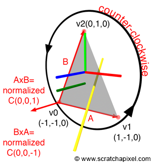
To determine the plane's normal—which also serves as the triangle's normal, as the triangle resides within the plane—we calculate the cross product of vectors \(AB\) and \(AC\). Since these vectors lie in the same plane (connecting the triangle's vertices), the resulting vector from the cross product, denoted as \(N\), represents the sought-after normal (see Figure 1). The operations are summarized in the following pseudocode:
Vec3f v0(-1, -1, 0), v1(1, -1, 0), v2(0, 1, 0);
Vec3f A = v1 - v0; // Edge 0
Vec3f B = v2 - v0; // Edge 1
Vec3f C = cross(A, B); // Triangle's normal
normalize(C);
The mathematical representation of these operations is as follows:
$$ \begin{align*} A &= v1 - v0 = (1 - (-1), -1 - (-1), 0 - 0) = (2, 0, 0)\\ B &= v2 - v0 = (0 - (-1), 1 - (-1), 0 - 0) = (1, 2, 0)\\ C &= A \times B = \\ C_x &= A_y \cdot B_z - A_z \cdot B_y = 0\\ C_y &= A_z \cdot B_x - A_x \cdot B_z = 0\\ C_z &= A_x \cdot B_y - A_y \cdot B_x = 2 \cdot 2 - 0 \cdot 1 = 4\\ \end{align*} $$After normalizing \(C\), we obtain the vector \((0, 0, 1)\), which is parallel to the positive \(z\)-axis. This outcome is expected, given that the vertices \(v0\), \(v1\), and \(v2\) are positioned in the \(XY\)-plane.
Coordinate System Handedness
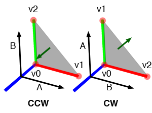
The order in which a triangle's vertices are defined significantly affects the orientation of the surface's normal. Defining vertices \(V_0\), \(V_1\), and \(V_2\) in a counter-clockwise order (CCW) results in a normal denoted by \(N\). Conversely, if the vertices were defined in a clockwise order (CW), the normal obtained from the cross product of the two edges (\(A=V_1-V_0\) and \(B=V_2-V_0\)) would point in the opposite direction, yielding \(-N\).
When creating a triangle in Maya, which uses a right-hand coordinate system, generating the triangle's vertices in a CCW order implies that the x-axis (\(V_0V_1\)) becomes \(A\), the y-axis (\(V_0V_2\)) becomes \(B\), and \(C\), the cross product \(A \times B\), aligns parallel to the z-axis (Figure 2). However, if the vertices are created in a CW order, then \(C\) will point along the negative z-axis. Creating vertices in CW order and computing \(N\) from the cross product \(A \times B\) is equivalent to computing the cross product \(B \times A\) when vertices are created in CCW with \(A=V_1-V_0\) and \(B=V_2-V_0\).
Imagine creating this triangle in a left-hand coordinate system, using the same vertices coordinates as in the right-hand coordinate system example (\(V_0 = (0,0,0)\), \(V_1=(1,0,0)\), and \(V_2=(0,1,0)\)). Following the same steps, we create vectors \(A\) (\(V_1-V_0\)) and \(B\) (\(V_2-V_0\)) and compute \(C\) (from \(A \times B\)). The result is \((0,0,1)\), identical to the right-hand coordinate system example, as the vertices' coordinates are the same. Hence, vectors \(A\) and \(B\), as well as the cross product \(A \times B\), are unchanged. By convention, the z-axis in the left-hand coordinate system points towards the screen (when the x-axis points to the right), aligning with our explanations on the handedness of coordinate systems. The cross product is an anti-commutative operation, as discussed in our lesson on Geometry.
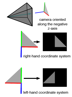
The next step is to render each of these triangles from a camera pointing down the negative z-axis. The results of these tests, shown in Figure 4, reveal that the two images do not appear the same, even though the triangles' vertices share the same coordinates. This discrepancy is undesirable, as the choice of a coordinate system's handedness should not alter the geometry's appearance from the camera's viewpoint. Ideally, a rendering should consistently depict the same image of a triangle, regardless of the handedness used. This issue, while not directly related to ray-triangle intersection tests, poses a significant challenge. Typically, we address it by mirroring the camera along the negative z-axis, including both its position and orientation, as illustrated in Figure 4.
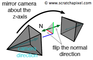
However, this adjustment changes the direction of both the camera and the triangle's normal compared to their orientations before the mirroring. Initially, in Figure 3, the camera's direction and the triangle's normal are opposite. After the adjustment, they point in the same direction. These vectors—the triangle's normal and the camera direction—are crucial for shading; thus, their relative orientations remain unchanged. The solution for the flipped triangle issue involves mirroring the camera and reversing the normal's direction. This adjustment is only required if the triangle was modeled in a left-hand coordinate system application but rendered in a right-hand coordinate system renderer, or vice versa. For instance, creating geometry in Maya and rendering it in RenderMan, which uses right- and left-hand coordinate systems, respectively.
The specific order and direction in which vertices are defined is referred to as winding.
With these tools at our disposal, we are well-equipped to tackle the ray-triangle intersection test using simple geometry.