Framing: The LookAt Function
Reading time: 19 mins.In this brief lesson, we will explore a straightforward yet effective method for positioning 3D cameras. To grasp the content of this lesson, familiarity with the concept of transformation matrices and the cross product between vectors is required. If you are not already acquainted with these concepts, you may wish to first review the lesson on Geometry.
Placing the Camera
Positioning the camera in a 3D scene is crucial. In most lessons from Scratchapixel, we typically set the camera's position and orientation (noting that scaling a camera is illogical) using a 4x4 matrix, often referred to as the camera-to-world matrix. However, manually configuring a 4x4 matrix can be cumbersome.
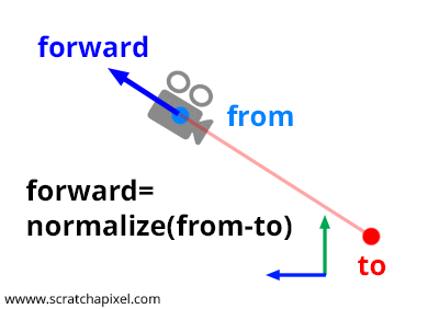
Fortunately, there is a method commonly known as the look-at method, which simplifies this process. The concept is straightforward. To establish a camera's position and orientation, you need a point in space for the camera's position and another point to define where the camera is aiming. Let's label our first point "from" and our second point "to".
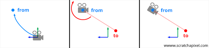
From these two points, we can easily create a world-to-camera 4x4 matrix, as we will demonstrate in this lesson.
Before proceeding, however, let's clarify a potential source of confusion. In a right-hand coordinate system, if you look along the z-axis, the x-axis points to the right, the y-axis points upward, and the z-axis points towards you, as depicted in the figure below.
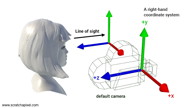
Thus, when envisioning a new camera setup, it seems natural to orient the camera as if viewing the right-hand coordinate system with the z-axis pointing towards the camera (as illustrated above). Because cameras are conventionally oriented in this manner, some texts (e.g., Physically Based Rendering / PBRT) suggest this orientation implies cameras are defined in a left-hand coordinate system, where the z-axis points away from you (in the same direction as the line of sight) when looking down the z-axis. While it's true that the right-hand coordinate system is standard, suggesting an exception for cameras could lead to confusion.
We prefer to consider that cameras operate within a right-hand coordinate system, like all other objects in our 3D application. However, we invert the camera's orientation at render time by "scaling" the ray direction by -1 along the camera's local z-axis when casting rays into the scene. As noted in the lesson Ray-Tracing: Generating Camera Rays, the ray-direction's z-component is set to -1 before transforming the ray direction vector by the camera-to-world matrix. This adjustment isn't exactly scaling; it merely reverses the ray direction vector along the camera's local z-axis.
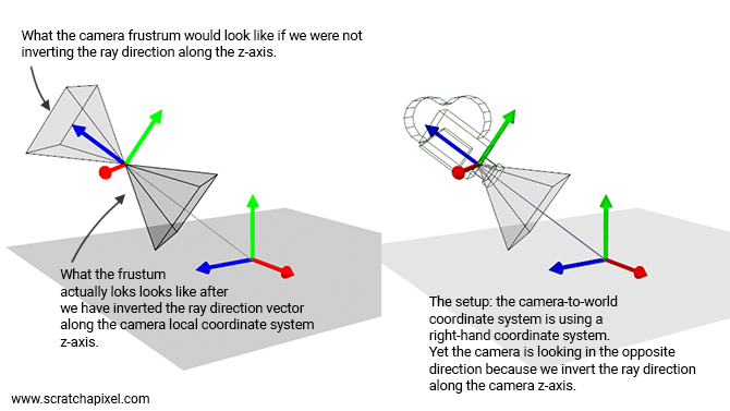
Bottom line: if your application uses a right-hand coordinate system, to maintain consistency, the camera should also be defined within a right-hand coordinate system, just like any other 3D object. However, as we cast rays in the opposite direction, it essentially appears as if the camera were looking down along the negative z-axis. With this clarification addressed, let's now explore how to construct this matrix.
Remember, a 4x4 matrix encodes the three axes of a Cartesian coordinate system. If this concept isn't clear, please revisit the lesson on Geometry. Note that there are two conventions to consider when dealing with matrices and coordinate systems. For matrices, you must decide between row-major and column-major representations. We will use the row-major notation. As for the coordinate system, you must choose between right-hand and left-hand systems. We will adopt a right-hand coordinate system. The fourth row of the 4x4 matrix (in row-major representation) encodes translation values.
$$ \begin{matrix} \color{red}{Right_x}&\color{red}{Right_y}&\color{red}{Right_z}&0\\ \color{green}{Up_x}&\color{green}{Up_y}&\color{green}{Up_z}&0\\ \color{blue}{Forward_x}&\color{blue}{Forward_y}&\color{blue}{Forward_z}&0\\ T_x&T_y&T_z&1 \end{matrix} $$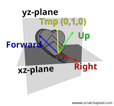
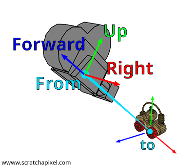
The naming of the axes of a Cartesian coordinate system is arbitrary. You could refer to them as x, y, and z, but for the sake of clarity in this lesson, we will name them right (for the x-axis), up (for the y-axis), and forward (for the z-axis), as illustrated in Figure 1. The process of constructing a 4x4 matrix from a pair of points, "from" and "to," can be summarized in four steps:
-
Step 1: Compute the forward axis. As shown in Figures 1 and 2, the forward axis of the camera's local coordinate system aligns with the line segment defined by the points from and to. A bit of geometry is enough to calculate this vector. You need to normalize the vector \(\text{From-To}\). Pay attention to the direction of this vector: it is \(\text{From-To}\), not \(\text{To-From}\). This operation can be performed with the following code snippet:
Vec3f forward = Normalize(From - To);
Let's now calculate the other two vectors.
-
Step 2: Compute the right vector. As we've learned from the lesson on Geometry, Cartesian coordinates are defined by three unit vectors that are perpendicular to each other. We also understand that if we take two vectors \(A\) and \(B\), they can be considered as lying in a plane. Furthermore, the cross product of these two vectors yields a third vector \(C\) that is perpendicular to that plane, and thus perpendicular to both \(A\) and \(B\). This property allows us to generate the right vector. The strategy involves using an arbitrary vector to calculate the cross vector between the forward vector and this arbitrary vector. The result is a vector that is necessarily perpendicular to the forward vector, which can then be utilized in our Cartesian coordinate system as the right vector. The code to compute this vector is straightforward, requiring only a cross-product between the forward vector and this arbitrary vector:
Vec3f right = crossProduct(randomVec, forward);
How should we select this arbitrary vector? In fact, this vector cannot truly be arbitrary, which is why the word is italicized. Consider this: if the forward vector is (0,0,1), then the right vector should be (1,0,0). This outcome is only achievable if we choose the vector (0,1,0) as our arbitrary vector. Indeed, \((0,1,0) \times (0,0,1) = (1,0,0)\), where the symbol \(\times\) denotes the cross product. Recall the formula for calculating the cross-product:
Also, note from this observation that the right vector always resides in the xz-plane. You might wonder how this is possible if applying a roll to the camera would place the right vector in a different plane? Indeed, direct application of a roll to the camera using the look-at method is not feasible. To incorporate camera roll, you would first need to create a matrix for rolling the camera (rotating the camera around the z-axis) and then multiply this matrix by the camera-to-world matrix constructed with the look-at method.
Here is the final code to compute the right vector:
Vec3f tmp(0, 1, 0); Vec3f right = crossProduct(tmp, forward);
It's important to be mindful of the vectors' order in the cross-product calculation. Recall that the cross-product operation is anti-commutative (for further details, refer to the lesson on Geometry). A helpful mnemonic for remembering the correct order is to consider the cross product of the forward vector (0,0,1) with the up vector (0,1,0), which we know should yield (1,0,0) and not (-1,0,0). Familiarity with the cross-product equations should easily reveal that the correct order is \(up \times forward\) and not the reverse. Now that we have the forward and right vectors, let's proceed to identify the "true" up vector.
-
Step 3: Compute the up vector. This step is straightforward: given two orthogonal vectors, the forward and right vectors, computing the cross product between these two vectors yields the missing third vector, the up vector. If the forward and right vectors are normalized, then the resulting up vector computed from the cross product will also be normalized (The magnitude of the cross product of \(u\) and \(v\) equals the area of the parallelogram determined by \(u\) and \(v\), \(\|u \times v\| = \|u\| \cdot \|v\| \cdot \sin \theta\)):
Vec3f up = crossProduct(forward, right);
Again, it's important to pay attention to the order of the vectors in the cross-product. We now have the three vectors that define the camera coordinate system. Let's proceed to construct our final 4x4 camera-to-world matrix.
-
Step 4: Setting the 4x4 matrix using the right, up, and forward vectors as basis vectors. The remaining task is to build the camera-to-world matrix itself. This involves replacing each row of the matrix with the appropriate data:
-
Row 1: replace the first three coefficients with the coordinates of the right vector,
-
Row 2: replace the first three coefficients with the coordinates of the up vector,
-
Row 3: replace the first three coefficients with the coordinates of the forward vector,
-
Row 4: replace the first three coefficients with the coordinates of the from point.
-
If the reason behind this setup is unclear, revisiting the lesson on Geometry may help. Below is the source code of the complete function, which computes and returns a camera-to-world matrix from two arguments, the from and to points. The function's third parameter (_up_) is the arbitrary vector used in the computation of the right vector. It is set to (0,1,0) in the main function, but you may need to normalize it for safety (in case a user inputs a non-normalized vector).
#include <cmath>
#include <cstdint>
#include <iostream>

struct float3
{
public:
    float x{ 0 }, y{ 0 }, z{ 0 };
    float3 operator - (const float3& v) const
    { return float3{ x - v.x, y - v.y, z - v.z }; }
};

void normalize(float3& v)
{
    float len = std::sqrt(v.x * v.x + v.y * v.y + v.z * v.z);
    v.x /= len, v.y /= len, v.z /= len;
}

float3 cross(const float3& a, const float3& b)
{
    return {
        a.y * b.z - a.z * b.y,
        a.z * b.x - a.x * b.z,
        a.x * b.y - a.y * b.x
    };
}

struct mat4
{
public:
    float m[4][4] = {{1, 0, 0, 0},  {0, 1, 0, 0}, {0, 0, 1, 0}, {0, 0, 0, 1}};
    float* operator [] (uint8_t i) { return m[i]; }
    const float* operator [] (uint8_t i) const { return m[i]; }
    friend std::ostream& operator << (std::ostream& os, const mat4& m)
    {
        for (int i = 0; i < 4; i++) {
            for (int j = 0; j < 4; j++) {
                os << m[i][j];
                if (j < 3) os << ", ";
            }
            if (i < 3) os << ",\n";
        }
        return os;
    }
};

void lookat(const float3& from, const float3& to, const float3& arbitraryUp, mat4& m)
{
    float3 forward = from - to;
    normalize(forward);
    float3 right = cross(arbitraryUp, forward);
    normalize(right);
    float3 up = cross(forward, right);

    m[0][0] = right.x,   m[0][1] = right.y,   m[0][2] = right.z;
    m[1][0] = up.x,      m[1][1] = up.y,      m[1][2] = up.z;
    m[2][0] = forward.x, m[2][1] = forward.y, m[2][2] = forward.z;
    m[3][0] = from.x,    m[3][1] = from.y,    m[3][2] = from.z;
}

int main()
{
    mat4 m;

    float3 up{ 0, 1, 0 };
    float3 from{ 1, 1, 1 };
    float3 to{ 0, 0, 0 };

    lookat(from, to, up, m);

    std::cout << m << std::endl;

    return 0;
}
This should produce:
0.707107, 0, -0.707107, 0, -0.408248, 0.816497, -0.408248, 0, 0.57735, 0.57735, 0.57735, 0, 1, 1, 1, 1
I stumbled upon some code that uses the following implementation for the LookAt method:
LINMATH_H_FUNC void mat4x4_look_at(mat4x4 m, vec3 const eye, vec3 const center, vec3 const up)
{
    vec3 f;
    vec3_sub(f, center, eye);
    vec3_norm(f, f);

    vec3 s;
    vec3_mul_cross(s, f, up);
    vec3_norm(s, s);

    vec3 t;
    vec3_mul_cross(t, s, f);

    m[0][0] =  s[0];
    m[0][1] =  t[0];
    m[0][2] = -f[0];
    m[0][3] =  0.f;

    m[1][0] =  s[1];
    m[1][1] =  t[1];
    m[1][2] = -f[1];
    m[1][3] =  0.f;

    m[2][0] =  s[2];
    m[2][1] =  t[2];
    m[2][2] = -f[2];
    m[2][3] =  0.f;

    m[3][0] =  0.f;
    m[3][1] =  0.f;
    m[3][2] =  0.f;
    m[3][3] =  1.f;

    mat4x4_translate_in_place(m, -eye[0], -eye[1], -eye[2]);
}
This method does not calculate the camera-to-world matrix, but rather the world-to-camera matrix—its inverse. Typically, this matrix is desired in programs that use real-time graphics APIs; it is often referred to as the view matrix. It is used in the vertex shader to transform vertices from world space to camera space. Therefore, using this method to directly obtain the world-to-camera matrix can be more convenient than the method provided above, which yields the camera-to-world matrix instead.
The code differs from the previously provided implementation in the following ways:
-
Firstly, the forward vector is calculated as
center - eye, which is the reverse of our previous approach. The resulting vector points from the camera to the target, more closely aligning with the concept of a forward vector. However, because this vector is in reverse order (compared to the one we've been using), terms in the subsequent cross products are reversed.Given:
-
eye= (0, 0, 1) -
center= (0, 0, 0) -
up= (0, 1, 0)
Calculate Right Vector
$$ \text{s} = \text{f} \times \text{up} = (0, 0, -1) \times (0, 1, 0) $$susing the cross product operationf × up:Using the cross product formula:
$$ \text{s} = \left((0)(0) - (-1)(1), (-1)(0) - (0)(0), (0)(1) - (0)(0)\right) = (1, 0, 0) $$The right vector
scorrectly points along the positive x-axis.Calculate Up Vector
$$ \text{t} = \text{s} \times \text{f} = (1, 0, 0) \times (0, 0, -1) $$tusing the cross product operations × f:Using the cross product formula:
$$ \text{t} = \left((0)(-1) - (0)(0), (0)(0) - (1)(-1), (1)(0) - (0)(1)\right) = (0, 1, 0) $$The new up vector
tremains aligned with the positive y-axis.In the end, as you can see, we are consistent in terms of the x and y axes with the results the
lookatmethod provides. -
-
Finally, when building or filling up the terms of the matrix, note that we apply them as if the matrix has been transposed. That's because, as mentioned in the lesson on geometry, assuming the matrix is orthogonal, the inverse of an orthogonal matrix is just its transpose. So, all you need to do to build the world-to-camera matrix is to transpose the coefficients of the camera-to-world matrix.
-
We invert the forward vector values because, as pointed out in the lesson, the camera needs to look down the negative z-axis.
-
Regarding the translation, you need to proceed as if you were multiplying the current matrix with a matrix whose translation values are set to
-eye[0], -eye[1], -eye[2]. This is essentially whatmat4x4_translate_in_placeaccomplishes. To be more precise, we don’t directly set the translation matrix for the eye position in this case. We know the camera-to-world translation values, given by theeyevector. However, since the matrix transforms vertices from world space to camera space, we need to transform the eye position in world space back into camera space. Thus,mat4x4_translate_in_placecan be seen as aTr * Mmultiplication, whereTris the translation matrix andMis our world-to-camera matrix. The resulting matrix is the translation matrix multiplied by our world-to-camera matrix.
Note the use of -eye (not eye) because we need to translate the eye position back to the origin, accounting for any rotation, scale, and translation that might already be applied to the world-to-camera matrix before this final translation step.
LINMATH_H_FUNC void mat4x4_translate_in_place(mat4x4 M, float x, float y, float z)
{
	vec4 t = {x, y, z, 0};
	vec4 r;
	int i;
	for (i = 0; i < 4; ++i) {
		mat4x4_row(r, M, i);
		M[3][i] += vec4_mul_inner(r, t);
	}
}
The code for mat4x4_translate_in_place can be a bit confusing because it follows OpenGL conventions, where matrices are column-major but each column of the matrix is stored in memory as a row of floats (in a contiguous fashion). This is just a note for those who will eventually look at the linked code. If you find yourself lost regarding the difference between row-major and column-major order, and how elements are stored in memory despite the conventions used (welcome to the club of utterly confused people!), check the chapter on Matrices in the Geometry lesson.
Overall, this approach, which allows you to calculate the world-to-camera matrix directly without needing to invert the camera-to-world matrix, is worth knowing.
Row-Major vs. Column-Major Matrices, Camera-To-World vs. World-To-Camera, and the GPU Pipeline
If you intend to use the result of the look-at method in the GPU rendering pipeline using an API such as DirectX, Vulkan, or Metal, please read the following paragraph.
A reader was confused by the fact that, in one resource from the Internet, the matrix resulting from the computation of the look-at method had its translation values in the rightmost column of the matrix rather than in its fourth row. As you know, and as we have repeated on many occasions, the same matrix can appear different due to the row- vs. column-major matrix convention (see the lesson on Geometry for an in-depth explanation). In essence, you can switch from one convention to another via a transpose operation (if the matrix is orthogoanl. See below).
Keep in mind that what we calculate in this lesson is the camera-to-world matrix. That is, the matrix that transforms the camera from its default position (at the world origin, looking down the z-axis) to its final position and orientation in the scene. A matrix that moves a camera around shouldn't have its scale values (diagonal of the matrix) other than (1,1,1). In other words, there's no reason to scale a camera. Indeed, you should never scale a camera. Remember, on Screatchapixel, we consistently use the row-major matrix convention. Nothing else.
However, when you use a GPU to render some geometry, the first step in the rendering pipeline is to convert the position of the triangle vertices from world space to camera space. This conversion is always done in the vertex shader. This matrix is the inverse of the matrix we calculated in this lesson. Therefore, if you need to use the work from this lesson in a program that uses a 3D real-time graphics API and the GPU to render your scene, what you will need to pass to the vertex shader is the world-to-camera matrix, which is the inverse of the camera-to-world matrix we have learned to calculate here.
As you probably remember from the lesson on Geometry, dealing with an orthogonal matrix, that is, a matrix that preserves right angles and vector lengths under transformation, the inverse of such a matrix is the matrix's transpose. This property is relevant because the camera-to-world matrix, by its very construction, should be orthogonal. This is due to the fact that we only deal with translation values and unit-length vectors for rotation, without incorporating any scaling or shearing. In other words, if you see a matrix in the GPU vertex shader that looks like the inverse of the matrix we've calculated, it's normal: that's because what you are looking at in this shader is our matrix inverse, that is, our matrix transposed. QED.
Now, things are more "twisted" in modern GPU APIs because they offer programmers control over which matrix convention is used in the shader. Users can now choose whether they prefer to work with row or column-major order matrices in the vertex or fragment shaders, whereas in the past, this option was not possible. All shaders in APIs such as Vulkan or older versions of DirectX always dealt with column-major matrices. So, if you are dealing with a modern 3D real-time API, you will need to see if the option that allows you to choose between one convention or the other is set. If not set, assume the column-major order convention. The code below shows how you can set the matrix convention to row-major, which again is not the default (the default is column-major for historical reasons):
layout(set = 0, binding = 0, row_major) uniform UBO {
    mat4 matrix;
} ubo;
Remember that:
-
We calculate here the camera-to-world matrix.
-
The GPU vertex shader expects the world-to-camera matrix to convert vertices from world to camera space.
-
Assuming your world-to-camera matrix doesn't have any scale (which it shouldn't), going from the camera-to-world to the world-to-camera matrix can be easily done by taking the camera-to-world matrix's transpose (no need for the computationally expensive inverse method here).
-
Modern GPU APIs allow you to decide in the shader which convention you wish to use for your matrix. So, you might want to check this too.
The Look-At Method Limitations
The look-at method is straightforward and generally effective for placing a camera in a 3D scene. However, it does have a notable limitation, particularly when the camera's orientation is vertical, either looking straight down or straight up. In such orientations, the forward axis aligns closely or even becomes parallel to the arbitrary axis employed in calculating the right axis. This alignment issue is most critical when the forward vector and the arbitrary axis are perfectly parallel, for example, when the forward vector is (0,1,0) or (0,-1,0). In these scenarios, the cross-product operation, which is pivotal in generating the right vector, fails to yield a valid result due to the lack of a perpendicular component between the parallel vectors.
Unfortunately, there's no straightforward fix for this issue. One practical approach is to detect when this situation occurs and manually set the vectors, leveraging the understanding of their expected configuration in such cases. A more sophisticated and elegant solution involves the use of quaternion interpolation. Quaternion interpolation offers a way to smoothly transition between orientations, avoiding the pitfalls of gimbal lock and the issue described here, by providing a continuous path between rotational states even when approaching vertical orientations. This method can maintain a stable and consistent camera orientation, circumventing the limitations of the cross-product in extreme cases. You can learn about this technique in the Camera Navigation Controls lesson.