Perspective Projection
Reading time: 7 mins.How Do I Find the 2D Pixel Coordinates of a 3D Point?
"How do I find the 2D pixel coordinates of a 3D point?" is one of the most common questions in 3D rendering on the Web. It is an essential question because it is the fundamental method for creating an image of a 3D scene. In this lesson, we will use the term rasterization to describe the process of finding 2D pixel coordinates of 3D points. In its broader sense, rasterization refers to converting 3D shapes into a raster image. A raster image, as explained in the previous lesson, is the technical term for a digital image; it designates a two-dimensional array (or rectangular grid, if you prefer) of pixels.
Don't be mistaken: different rendering techniques exist for producing images of 3D scenes. Rasterization is only one of them. Ray tracing is another. Note that all these techniques rely on the same concept to create that image: the idea of perspective projection. Therefore, for a given camera and a given 3D scene, all rendering techniques produce the same visual result; they just use different approaches to achieve that result.
Also, computing the 2D pixel coordinates of 3D points is only one of the two steps in creating a photorealistic image. The other step is the process of shading, in which the colors of these points are computed to simulate the appearance of objects. You need more than just converting 3D points to pixel coordinates to produce a "complete" image.
To understand rasterization, you first need to be familiar with a series of essential techniques that we will also introduce in this chapter, such as:
-
The concept of local vs. global coordinate systems.
-
Learning how to interpret 4x4 matrices as coordinate systems.
-
Converting points from one coordinate system to another.
Read this lesson carefully, as it will provide you with the fundamental tools that almost all rendering techniques are built upon.
We will use matrices in this lesson, so read the Geometry lesson if you are uncomfortable with coordinate systems and matrices.
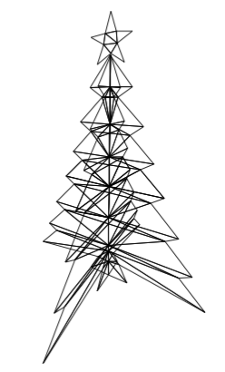
We will apply the techniques studied in this lesson to render a wireframe image of a 3D object (shown in the adjacent image). The files for this program can be found in the Scratchapixel GitHub repo (link in the table of content above), as usual.
A Quick Refresher on the Perspective Projection Process

We have already discussed the perspective projection process in several lessons, such as in the chapter The Visibility Problem from the lesson "Rendering an Image of a 3D Scene: An Overview." However, let's quickly recap what perspective projection is. Simply put, this technique is used to create a 2D image of a 3D scene by projecting points (or vertices) that make up the objects of that scene onto a canvas.
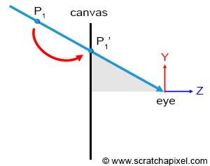
This technique is analogous to how the human eye perceives the world. Since we view the world through our eyes, images created with this technique tend to appear natural and "real." Think of the human eye as just a "point" in space (Figure 2). Of course, the eye is not actually a point; it is an optical system that converges rays onto a small surface—the retina. What we perceive is the result of light rays, reflected by objects, traveling to and entering the eye. Similarly, one way to render an image of a 3D scene in computer graphics (CG) is to project vertices onto the surface of the canvas (or screen) as if the rays were extending along straight lines from the vertices to the eye.
It is crucial to understand that perspective projection is an arbitrary method of representing 3D geometry on a two-dimensional surface. This method is most commonly used because it mimics one of the essential properties of human vision—foreshortening: objects farther away appear smaller than those that are closer. However, as noted in the Wikipedia article on perspective), it is essential to recognize that the perspective projection is only an approximate representation of what the eye sees, depicted on a flat surface, such as paper. The key term here is "approximate."

In the aforementioned lesson, we also explained how to compute the world coordinates of a point located in front of the camera (and enclosed within the viewing frustum of the camera, thus visible to the camera) using a simple geometric construction based on the properties of similar triangles (Figure 3). We will review this technique again in this lesson. The equations to compute the coordinates of projected points can be conveniently expressed as a 4x4 matrix. The computation involves a series of operations on the original point's coordinates; this is what you will learn in this lesson. By expressing the computation as a matrix, these operations can be reduced to a single point-matrix multiplication. This approach's main advantage is that it represents this critical operation in a compact and easy-to-use form. As we will demonstrate in the lesson devoted to the perspective and orthographic projection matrices, the perspective projection process and its associated equations can be expressed in the form of a 4x4 matrix, known as the perspective projection matrix. Multiplying any point whose coordinates are expressed with respect to the camera coordinate system with this perspective projection matrix will yield the position (or coordinates) of that point on the canvas.
In CG, transformations are almost always linear. However, it is essential to note that the perspective projection, part of the broader family of projective transformations, is a non-linear transformation. If you're interested in a visual explanation of which transformations are linear and which are not, this YouTube video provides a clear demonstration.
In this lesson, we will explore how to compute the 2D pixel coordinates of a 3D point without using the perspective projection matrix. To achieve this, we will need to learn how to "project" a 3D point onto a 2D drawable surface (which we will refer to as a canvas) using some simple geometric rules. Once we grasp the mathematics of this process (and all other steps involved in computing these 2D coordinates), we will be ready to study the construction and use of the perspective projection matrix: a tool used to simplify the projection step (and only the projection step). This will be the topic of our next lesson.
Some History
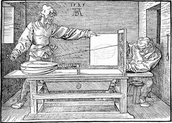
The mathematics behind perspective projection began to be understood and mastered by artists towards the end of the fourteenth century and the beginning of the fifteenth century. These artists played a significant role in educating others about the mathematical basis of perspective drawing through books that they authored and illustrated themselves. A notable example is "The Painter's Manual" published by Albrecht Dürer in 1538 (the illustration above is from this book). Two concepts broadly characterize perspective drawing:
-
Diminution: Objects appear smaller as their distances from the viewer increase.
-
Foreshortening: This is the impression, or optical illusion, that an object or distance appears shorter than it is because it is angled towards the viewer.
Another principle of foreshortening is that while vertical lines remain parallel, non-vertical lines converge towards a perspective point, making them appear shorter. These effects create a sense of depth, which helps to evaluate the distance of objects from the viewer. Today, the same mathematical principles are utilized in computer graphics to create a perspective view of a 3D scene.