Procedural Texturing
Reading time: 11 mins.Procedural Texturing
Texturing in computer graphics is a very common technique used to add details to the surface of an object. The principle is similar to wallpaper in a way. The only thing you can do with objects is to render them as diffuse objects for example using a solid color for the entire object. The alternative solution is to break the object into smaller parts and give a unique albedo value or color to each part of the object. Breaking the object to follow the form of the texture details you want to apply to the surface of an object is of course time consuming and while it works if the pattern applied is only made out of solid colors, it doesn't work if you wish to apply some gradients of colors on the surface of the object.
Texturing is the solution to these problems. As mentioned, the principle is the same as wallpaper. Some complex pattern is painted on the surface of a flat sheet of paper, and the paper is then laid on the surface of the walls. In CG, the pattern applied to the surface of an object, can either be an image or can also be generated using some sort of mathematical equation. The second technique is called procedural texturing. We will study this technique in this lesson. A lesson devoted to the topic of texturing using images can be found later in this section.
As explained in the lesson Introduction to Polygon Meshes, to apply any sort of image or pattern procedurally generated on the surface of an image, we need texture coordinates. Texture coordinates are just the coordinates of the object vertices in a 2D space, which we generally call the uv or st or simply texture space. This process is explained in detail in the aforementioned lesson. We assume the reader is already familiar with this concept. Texture coordinates give us a frame of reference with which we can work and create all sorts of 2D procedural patterns. Texture coordinates as we know are defined in a 2D space. Along the x-axis, we generally denote the coordinate, the s- or v- coordinate. Along the y-axis, the texture coordinates are denoted as t- or v-coordinate. In this lesson, we will stick to the conventions and t.
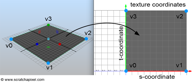
The image above shows a 3D plane and its associated texture coordinates. As you can see, the 4 vertices of the quad fill up the entire set or coordinate space, which generally goes from 0 to 1 but this is not a limitation, texture space is not limited to the range [0,1]. However, for now, we will just look at this simple most basic, and common case. Later on in the chapter, we will see what happens when the quad in 3D space doesn't have a square shape in texture space.
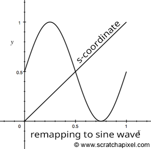
Let's only consider the texture coordinate along the x-axis or horizontal axis. At v0 the value of the s-coordinate is 0 and for v1, the value of the s-coordinate is 1\. The s-coordinate of any between v0 and v1 can be computed by linearly interpolating the s-coordinates of v0 and v1 respectively (this assumes that we know the distance from at least v0 or v1). In our particular case, the s-coordinate simply from v0 to v1 simply varies linearly between 0 (the s-coordinate value of v0) and 1 (the s-coordinate of v1). Though if we remap this simple linear function into some sort of mathematical function such as a cosine or sine function, we then obtain a more complex pattern (a sine wave) which we can then apply to the surface of the object in the image below. A sine wave varies in the range [-1,1] and since colors can't be negative we can't directly use the result of this remapping as a color but with another simple remapping of the result, we can get a value that fits in the range [0,1]. Note though that our s-coordinates only go from 0 to 1\. However, to complete a full turn around the unit circle we need to go from 0 to \(2\pi\). Thus we also need to remap the s-coordinates to the range [0,\(2\pi\)]. Finally, we can control the number of sine waves across the width of the quad by scaling this remapped s-coordinate up or down. Here is the code we used to produce the image on the right below:
float scaleS = 5; // scale of the pattern
float pattern = (sin(hitTexCoordinates.x * 2 * M_PI * scaleS) + 1) * 0.5; // compute sine wave pattern
hitColor += vis * pattern * lightIntensity * std::max(0.f, hitNormal.dotProduct(-lightDir));
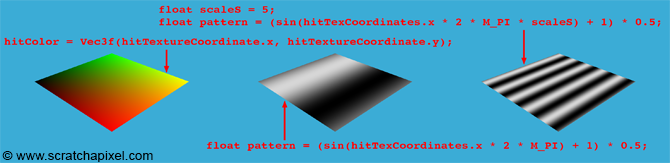
We produced a pattern by using the s-coordinate. But we can also produce a similar pattern in the "perpendicular" direction using the t-coordinate. By combining or multiplying the result of one by the other we can also get some more interesting two-dimensional patterns as shown in the following image:
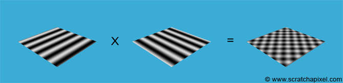
float scaleS = 5, scaleT = 5; // scale of the pattern
float pattern = (cos(hitTexCoordinates.y * 2 * M_PI * scaleT) * sin(hitTexCoordinates.x * 2 * M_PI * scaleS) + 1) * 0.5; // compute sine wave pattern
hitColor += vis * pattern * lightIntensity * std::max(0.f, hitNormal.dotProduct(-lightDir));
Creating a checkerboard pattern is also quite simple. To do so we will rely on the fmod function from the C++ library:
double fmod (double number, double denom);
The function returns the floating-point remainder of numer/denom (rounded towards zero):
fmod = number - tquot * denom
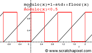
Where tquot is the truncated (i.e., rounded towards zero) result of: numer/_denom_. If we set the number to be one of the texture coordinates and set denim to be 1, then we get a function like the one plotted in Figure 2 (black). As you can see, we get some sort of function that keeps repeating itself. We can use the result of this function to make another test, and return true if the function is lower than 0.5 and false otherwise (Figure 2, in red):
float pattern = fmod(hitTextureCoordinates.x * scaleS, 1) < 0.5;
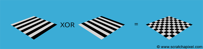
If we do the same thing for the t-coordinate and combine the result of the two functions using the ^ or bitwise exclusive-Or (XOR operator), then we get a checkerboard pattern:
inline float modulo(const float &x)
{
    return x - std::floor(x);
}
...
float pattern = (modulo(hitTexCoordinates.y * scaleT) < 0.5) ^ (modulo(hitTexCoordinates.x * scaleS) < 0.5);
Though note that we haven't used the C++ fmodf() function. The reason is that this function doesn't work for us when the numbers are negative. Indeed if x is equal to -1.1 we would like the function to return 0.9, so that the function is continuous as we switch from negative to positive numbers. Though the C++ function returns -0.1 instead. The solution is to write our own function, taking advantage of the C++ std::floor() which returns -2 when x is equal to -1.1 for example. And -1.1 - - 2 returns 0.9 as required.
XOR: This operation is performed between two bits (a and b). The result is 1 if either one of the two bits is 1, but not in the case that both are. Therefore, if neither or both of them is equal to 1 the result is 0.
0^0=0
0^1=1
1^0=1
1^1=0
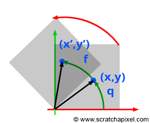
It is also quite easy to rotate the pattern. The texture coordinates are just 2D coordinates. Rotating a point (or texture coordinates) around the center of the texture coordinate system origin is simple. Let's assume that we first rotate a point by an angle \(q\). When then want to rotate this point even further by an angle \(f\) (as shown in figure 3).
$$ \begin{array}{l} x &=& r \cos q,\\ y &=& r \sin q\\ x' &=& r \cos ( q + f )\\ &=& r \cos q \cos f - r \sin q \sin f,\\ y' &=& r \sin ( q + w )\\ &=& r \sin q \cos f + r \cos q \sin f. \end{array} $$Where (x, y) is the point's original coordinates, and (x', y') are the coordinates of the new point. The trick here is to notice that \(r\cos q\) and \(r\sin q\) are nothing else than the original point's coordinates (in our example, the texture coordinates that we want to rotate). Therefore if we replace these terms with the coordinates (x, y) in the above equations, we get:
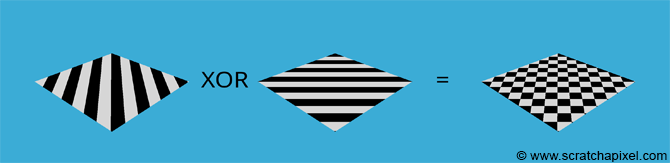
$$ \begin{array}{l} x' &=& x \cos f - y \sin f,\\ y' &=& y \cos f + x \sin f. \end{array} $$Let's use this finding in our code to rotate the texture coordinates (you can set the angle to whatever you like):
// compute the pattern
float angle = deg2rad(45);
float s = hitTexCoordinates.x * cos(angle) - hitTexCoordinates.y * sin(angle);
float t = hitTexCoordinates.y * cos(angle) + hitTexCoordinates.x * sin(angle);
float scaleS = 5, scaleT = 5;
float pattern = (modulo(s * scaleS) < 0.5) ^ (modulo(t * scaleT) < 0.5);
You can create a great variety of patterns using this technique. All you need to do is find clever ways of using mathematical equations to create such patterns. Try now to create your own (if you search on the web for procedural texturing, you should find more pattern examples). Noise which is a term you may have heard about already, is another kind of procedural pattern. A lesson is specifically devoted to studying the creation of noise patterns.
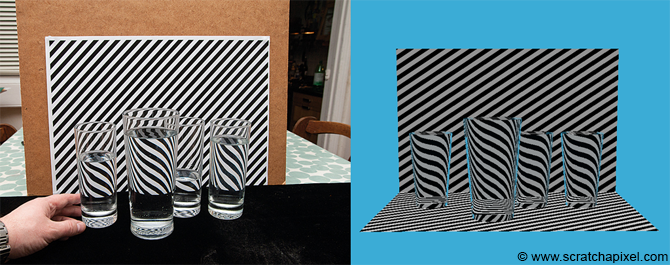
In the image below, we used a combination of the techniques we learned in this lesson. Diffuse lighting, procedural texturing, reflection, and refraction. Notice how the reflection of the stripes in the water on the right matches the refraction in the real glasses in the image on the left.
Aliasing and Anti-Aliasing
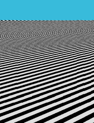
The problem with texturing and especially the kind of pattern we created in this lesson is that as the pattern becomes smaller and smaller in the distance, there is a point when there is not enough resolution in the image to differentiate the black and white lines from each other. In nature, this problem arises as well because even human eyes have a limited resolution. Though nature does things well. When a pattern becomes so small that we can't see what it is made of, the colors of the pattern generally sort of elegantly blend. In computer graphics, things are very different. Rather than being a composite of the pattern's colors, each pixel in the image picks up one color of the pattern instead. Because pixels are regularly spaced, if the pattern is also regular, we generally end up with some other strange pattern that has nothing to do with the original one. With regular stripes, this often gives an effort called the moire pattern which you can see an example of in the image on the right. The problem of not having a resolution in the image to properly resolve the fine details in the distance and the visual artifact this produces is called aliasing. This phenomenon is very well studied and pretty well understood. It finds its root in signal processing theory which is a very large (and reasonably complex) field of science. Solving aliasing though is a complex problem for which we don't have the perfect miracle solution. Though generally, you should know that it is naturally called anti-aliasing. It is the art (as it is as much an art as a science) of fighting to alias.
Aliasing itself and everything else you need to know about it to understand it is a very large topic. We won't even cover this topic in this first section, as it relies on signal processing theory. Teaching signal processing on its own is a very ambitious undertaking, which we will tackle at some point. It is enough for you, for now, to know about the term aliasing and understand that using procedural texturing as well as any sort of texturing techniques in fact, can produce aliasing.