Light and Shadows
Reading time: 9 mins.As mentioned in the previous chapter, this is merely a high-level introduction to light and shadows. Readers interested in studying this topic further are invited to read the lessons A Creative Dive into BRDF, Linearity, and Exposure and Introduction to Lighting. While these lessons are also part of the beginner section, they delve deeper into the topic of light implementation. You can then continue with the lessons from the advanced section.
Structure of this Chapter
In this chapter, we will learn how shadows are added to an image.
Lights & Shadows
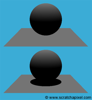
In the adjacent image, we can see a diffuse sphere and a diffuse plane illuminated by a directional light source. What's missing now in this image to make it more realistic is the shadow of the sphere on the plane. Fortunately, simulating the action of objects casting shadows on other objects in the scene is pretty straightforward in computer graphics (CG). However, it depends on the algorithm you are using to solve the visibility problem.
-
If you use rasterization, adding shadows to the scene cannot easily be done in one single pass. It requires precomputing the visibility of objects from the point of view of the light, which is stored in a special sort of image called a shadow map. You need to compute one shadow map per light in the scene, and this process needs to happen before you render the final image. We are planning to write a lesson on this technique in the future.
-
If you use ray tracing, computing shadows can be done while the main image is being rendered (it doesn't require precomputing a special image such as a shadow map). All we need to do is cast a ray from the object visible through a particular pixel of the frame, from the point of intersection to the light source. If this ray, which we call a shadow ray, intersects another object on its way to the light, then the point that we are shading is in the shadow of that object.
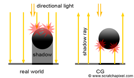
As mentioned many times before, in the real world, light travels from the light source to the eye. Shadows are the consequence of some objects along the light path blocking the light from reaching another surface that is located further along the way. Though, as you know by now, in CG, it is more efficient to trace the path of light from the eye to the light source. Thus, we first trace a camera or primary ray, then find an intersection point (the surface that is visible for the pixel from which the primary ray was cast), and then trace a shadow ray from that point of intersection to the light. The difference between what happens in nature and how we compute shadows in CG is shown in Figure 2.
Adding shadows is simple in a ray tracer. If the primary ray intersects an object, we then compute the intersection point and trace one more ray in the light direction (or more precisely, in the opposite direction of the light). This is simple since we already have all the code we need to compute the intersection of a ray with the objects making up the scene. For now, we will only learn how to add shadows from a directional light source. Later in this chapter, we will learn how to do the same thing for spherical lights. Here is the code:
Vec3f castRay(
    const Vec3f &orig, const Vec3f &dir,
    const std::vector<std::unique_ptr<Object>> &objects,
    const std::unique_ptr<DistantLight> &light,
    const Options &options)
{
    Vec3f hitColor = options.backgroundColor;
    IsectInfo isect;
    if (trace(orig, dir, objects, isect)) {
        Vec3f hitPoint = orig + dir * isect.tNear;
        Vec3f hitNormal;
        Vec2f hitTexCoordinates;
        isect.hitObject->getSurfaceProperties(hitPoint, dir, isect.index, isect.uv, hitNormal, hitTexCoordinates);
        Vec3f L = -light->dir;
        IsectInfo isectShad;
        bool vis = !trace(hitPoint + hitNormal * options.bias, L, objects, isectShad, kShadowRay);
        hitColor = vis * isect.hitObject->albedo * light->intensity * light->color * std::max(0.f, hitNormal.dotProduct(L));
    }

    return hitColor;
}
As you can see, we just call the trace function again (line 16) and set the variable vis to false if the trace function returns true (the intersection point is in shadow, thus the point is not illuminated by the directional light source) and true otherwise (the intersection point is not in shadow, thus the point is illuminated by the light source). All that is left to do is multiply the color of the intersection point by the result of this variable. If the point is in shadow, the point is black. If vis is set to true, then the color of the point is left unchanged (line 17).
Optimizations
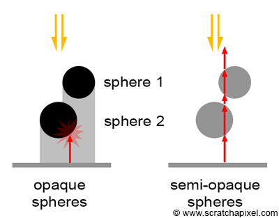
Note that when we compute whether a point is in the shadow of an object, the order in which the objects are intersected by the shadow ray does not matter. It does not matter if the object that the shadow ray intersects is not the closest object to the ray's origin. All we care about in this case of a shadow ray is to know if the ray intersects any object at all; in which case, the point from which the shadow ray was cast is in shadow. Practically, this means that for shadow rays, we could very well return from the trace function as soon as we intersect one object in the scene. This can potentially save some computation time.
However, this optimization is only possible if all the objects in the scene are fully opaque. If some of the objects are transparent, then light rays that are potentially being attenuated while traveling through these semi-transparent objects should continue traversing the objects until they either encounter an opaque object on their way to the light or reach the light itself (only in the case of spherical lights, not in the case of distant light which is assumed to be located at infinity). In this section, we will not show how to handle semi-transparent objects for shadow rays. Trying to optimize the code for shadow rays if you plan to support semi-transparent objects later on is not worth the effort but is left as an exercise if you wish to explore it.
Shadow-Acne: Avoiding Self-Intersection
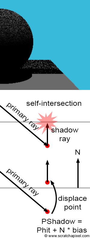
One common problem when using ray tracing to compute shadows is known as shadow-acne, which can be seen in the adjacent image (top). This visual artifact appears as small black dots on the surface of objects. Due to some small numerical errors, introduced by the finite precision of numbers in our 3D engine, sometimes the intersection point is not directly above the surface, but slightly below. When this happens and a shadow ray is cast in the light direction, instead of intersecting no object at all or some other object above the object's surface, the shadow ray intersects the surface from which it is cast. In other words, we have a case of self-intersection. Although an object can very well cast a shadow on itself, in this particular case, it is a mistake, as it only happens because the intersection point is below the surface rather than just on the surface. This situation is depicted in figure 4 (middle). The primary ray intersects a surface, but the point of intersection computed from the ray origin and direction, as well as the intersection distance \(t\), happens to be slightly below the surface rather than just on top of it. Shooting a shadow ray from that position leads to the shadow ray intersecting the surface that the point should be on, marking the point as being in shadow.
Several methods can be used to alleviate this problem. One solution is to use double-precision rather than single-precision floating-point numbers, i.e., using double instead of float. Though this doesn't eliminate the problem, it makes it less likely to occur. A simpler and more robust solution consists of systematically displacing the origin of the shadow ray in the direction of the surface normal to move it above the surface (Figure 4, bottom). The amount by which you displace or move the point in the normal direction is left to the user and can be tweaked on a scene-by-scene basis. This value is often referred to in ray-tracers as shadow bias.
The term shadow bias is also used with shadow maps. Check the lesson on shadow maps.
In code, you would get:
struct Options
{
    ...
    float bias = 1e-4;
};

Vec3f castRay(...)
{
    ...
    bool vis = !trace(hitPoint + hitNormal * options.bias, L, objects, isectShad, kShadowRay);
    ...
}
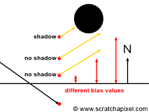
As you can see, the bias is generally a very small value. The amount of bias required depends on different factors such as the scene scale, the curvature of objects, the distance of objects to the camera, etc. As mentioned before, tweaking the bias is the easiest way of getting rid of shadow-acne, though it first needs to be adjusted on a scene-to-scene basis. More importantly, by changing the actual position of the point from which the shadow ray is cast, we get a result which is slightly different from what we would get if we had cast the ray from the "actual" point on the surface. The higher the bias, the larger the difference between the shadow we should get and the one that appears in the image (as shown in Figure 5). Tweaking the bias value is thus a balancing act. We want it high enough so that no acne appears in the final frame, while keeping it as small as possible to reduce the effect of shadow bias (this technique of pushing the ray below or above the surface is also used when casting reflection or refraction/transmission rays, as discussed in the chapter on simulating reflection and refraction).