About the Projection Matrix, the GPU Rendering Pipeline and Clipping
Reading time: 18 mins.Update
In 2024, I added the previous chapter to this lesson: Lost? Let's Recap With Real-World Production Examples. In that chapter, we mentioned many concepts related to the GPU vertex processing pipeline, which are only introduced in this chapter. If you were courageous enough to read the previous chapter in full but didn't understand everything due to a lack of knowledge regarding the GPU graphics pipeline, read this chapter and then revisit the previous one. I also amended this chapter in 2024 with slightly more information about GPUs, while waiting for a lesson solely devoted to how they are built and how they work.
What Will We Study in This Chapter?
In the first chapter, we discussed the crucial role in the GPU rendering pipeline that projection matrices play. We highlighted the existence of two types of GPU rendering pipelines: the older "fixed-function pipeline" and the newer, often referred to as the "programmable rendering pipeline." We delved into the process of clipping, which involves discarding or trimming primitives that fall outside or on the boundaries of the frustum, and how this occurs during the transformation of points by the projection matrix. Additionally, we clarified that projection matrices actually transform points from camera space to homogeneous clip space, not to NDC (Normalized Device Coordinate) space. Now, it's time to delve deeper into these subjects. We will explain the mechanism of clipping during the transformation process, define what clip space entails, and review the application of projection matrices in both the old and new GPU rendering pipelines.
Clipping and Clip Space
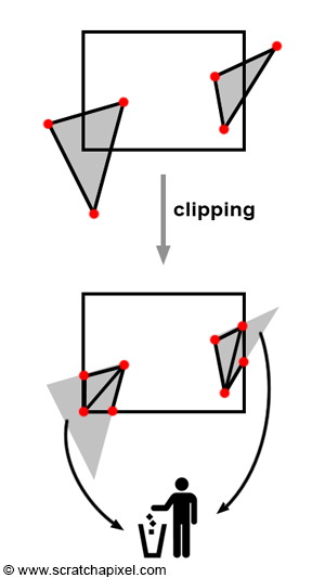
Let's briefly recall that the primary goal of clipping is to "reject" geometric primitives that are behind the eye or positioned exactly at the eye (which would result in division by zero during the perspective divide process, an undesirable outcome) and, more broadly, to trim parts of geometric primitives that lie outside the viewing area (further details on this topic can be found in Chapter 2). This viewing area is delineated by the truncated pyramid shape of the perspective or viewing frustum. Trimming is not an absolute requirement of any rendering system; it is more of an optimization step. After all, why should we be processing geometry that's not visible on the screen? And every nanosecond saved takes us a step closer to real-time rendering. It's important to note that this process can lead to the creation of more triangles than were initially present in the scene, as illustrated in Figure 1.
The most commonly used clipping algorithms include the Cohen-Sutherland algorithm for lines and the Sutherland-Hodgman algorithm for polygons. It turns out that clipping is more efficiently executed in clip space than in camera space (before vertices are transformed by the projection matrix) or Normalized Device Coordinates or NDC (after the perspective division). It's crucial to remember that when points are transformed by the projection matrix, they are first processed as they would be with any other 4x4 matrix. The transformed coordinates are then normalized, meaning the x, y, and z coordinates of the transformed points are divided by the transformed point's z-coordinate. Clip space refers to the space in which points exist just before they undergo normalization.
In summary, the process on a GPU unfolds as follows:
-
Points are transformed from camera space \(\rightarrow\) clip space, and this happens in what we call the vertex shader on the GPU. The input vertex is converted from Cartesian coordinates to homogeneous coordinates, where its w-coordinate is set to 1. The predefined
gl_Positionvariable (in GLSL language), where the transformed point is stored, also represents a point in homogeneous coordinates. However, when the input vertex is multiplied by the projection matrix, the normalization step has not yet occurred.gl_Positionis in homogeneous clip space. -
After all vertices have been processed by the vertex shader, triangles with vertices now in clip space undergo clipping.
-
Once clipping is complete, all vertices are then normalized. That is, the x, y, and z coordinates of each vertex are divided by their respective w-coordinate, marking the occurrence of the perspective divide. Our vertex is now expressed again in terms of Cartesian coordinates. In the previous chapter, we've shown the mechanism by which the perspective matrix, due to the way it is designed, effectively converts points into NDC space. This is a space in which all resulting visible vertices on the screen have their respective x- and y-coordinates in the range \([-1, 1]\), and the depth values also in the range \([-1, 1]\) (though be mindful that some APIs, such as Vulkan and OpenGL, will eventually remap them at some point in the pipeline to the range \([0, 1]\), but that's a different topic).
After the normalization step, points that are visible to the camera fall within the range \([-1,1]\) in both the x and y dimensions. This is part of the final stage of the point-matrix multiplication process, where the coordinates are normalized as mentioned. Again, how this happens is detailed in the previous chapter, but remember that the projection perspective matrix is designed so that when a point is multiplied by it, the resulting point (expressed in Homogeneous coordinates) has a w-coordinate that holds the vertex's z-coordinate value from camera space (more precisely, its negative z-coordinate value, as all points in front of the camera in camera space have a negative z-coordinate, and we want to negate that value to work with positive z-values). During the conversion from Homogeneous coordinates back to Cartesian coordinates, we divide the point's x, y, and z-coordinates (which have been transformed by the perspective matrix at this point) by the point's w-coordinate, which effectively holds the point's original z-coordinate. This is how the perspective divide is effectively done. The conversion process from Homogeneous to Cartesian looks like so:
$$ \begin{align*} -1 \leq \dfrac{x'}{w'} \leq 1 \\ -1 \leq \dfrac{y'}{w'} \leq 1 \\ -1 \leq \dfrac{z'}{w'} \leq 1 \\ \end{align*} $$Hence, we can also express this as:
$$ \begin{align*} -w' \leq x' \leq w' \\ -w' \leq y' \leq w' \\ -w' \leq z' \leq w' \\ \end{align*} $$And so, prior to the Homogeneous \(\rightarrow\) Cartesian conversions, we can see that the point's x, y, and z coordinates are all contained within the same range defined by \([-w_c, w_c]\). By the way, in technical resources and graphic API specifications, you will often see these written as:
$$ \begin{align*} -w_c &\leq x_c \leq w_c \\ -w_c &\leq y_c \leq w_c \\ -w_c &\leq z_c \leq w_c \\ \end{align*} $$Where the subscript \(c\) stands for clip space. Note that \(w_c\) should be greater than 0 at this stage (guaranteeing no division by zero drama).
These equations are mathematically sound, and they can be used to determine whether a vertex is visible on the screen. If all of its x, y, and z coordinates are within the range \([-w_c, w_c]\), then the vertex is visible. The clip space for any given vertex can be visualized as a cube whose minimum and maximum extents are \(\{-w_c, -w_c, -w_c\}\) and \(\{w_c, w_c, w_c\}\), respectively. However, note also that each point is likely to have its own unique clip space (because each set of x, y, and z coordinates is likely to have a different w value). In other words, every vertex exists within its own clip space and must "fit" within it.
This lesson focuses solely on projection matrices. All that is necessary to understand in this context is where clipping occurs in the vertex transformation pipeline and the definition of clip space, which we have just explained. Further details will be covered in lessons devoted specifically to the Sutherland-Hodgman and Cohen-Sutherland algorithms.
The "Old" Point (or Vertex) Transformation Pipeline
The fixed-function pipeline is now deprecated in OpenGL and modern graphics APIs (Vulkan, DirectX, Metal) are all using a programmable pipeline. It is advised not to use it anymore. Instead, use the "new" programmable GPU rendering pipeline. This section is retained for reference purposes and because you might still encounter some articles on the Web referencing methods from the old pipeline.
The term "vertex" is preferred when discussing the transformation of points (vertices) in OpenGL (or Vulkan, DirectX, Metal). In the old fixed-function pipeline, OpenGL offered two modes for altering the camera's state: GL_PROJECTION and GL_MODELVIEW. GL_PROJECTION was used for setting the projection matrix itself. As we have learned (see the previous chapter), this matrix is constructed from the left, right, bottom, and top screen coordinates (determined by the camera's field of view and near clipping plane), as well as the near and far clipping planes (parameters of the camera). These parameters delineate the camera's frustum shape, and all vertices or points within this frustum are visible. In OpenGL, these parameters were specified through a call to glFrustum (an implementation of which was shown in the previous chapter):
glFrustum(float left, float right, float bottom, float top, float near, float far);
The GL_MODELVIEW mode was used to set the world-to-camera matrix. A typical sequence of calls in an OpenGL program to set the perspective projection matrix and the model-view matrix would be:
glMatrixMode(GL_PROJECTION);
glLoadIdentity();
glFrustum(l, r, b, t, n, f);
glMatrixMode(GL_MODELVIEW);
glLoadIdentity();
glTranslate(0, 0, 10);
...
Initially, the GL_PROJECTION mode is activated (line 1). Then, to configure the projection matrix, a call to glFrustum is made, providing the left, right, bottom, and top screen coordinates, along with the near and far clipping planes as arguments. After setting up the projection matrix, the mode is switched to GL_MODELVIEW (line 4). In essence, the GL_MODELVIEW matrix can be considered a combination of the "VIEW" transformation matrix (the world-to-camera matrix) with the "MODEL" matrix (the transformation applied to the object, or the object-to-world matrix). There was no separate concept of the world-to-camera transform apart from the object-to-world transform; both were amalgamated in the GL_MODELVIEW matrix.
$$GL\_MODELVIEW = M_{object-to-world} \times M_{world-to-camera}$$Initially, a point \(P_w\) in world space is transformed into camera space (or eye space) using the GL\_MODELVIEW matrix. The resultant point \(P_c\) is then projected onto the image plane using the GL\_PROJECTION matrix, resulting in a point in homogeneous coordinates, where the w-coordinate contains the z-coordinate of point \(P_c\) (or more precisely, \(-z\), to turn the initially negative z-coordinate into a positive one).
The Vertex Transformation Pipeline in the New Programmable GPU Rendering Pipeline
The pipeline in the new programmable GPU rendering pipeline remains largely similar to the old pipeline, but with a significant difference in setup. In this updated pipeline, the concepts of GL_MODELVIEW and GL_PROJECTION modes no longer exist. Instead, this functionality can now be custom-programmed within a vertex shader. As outlined in the first chapter of this lesson, the vertex shader acts as a mini-program that dictates how the GPU processes the vertices of the scene's geometry. This means all vertex transformations, including the world-to-camera transformation and, more critically, the projection transformation, should be executed here. It's important to note that a program utilizing the OpenGL or Vulkan or DirextX or Metal API won't generate an image unless both the vertex and its corresponding fragment shader are defined. The simplest vertex shader might look something like this:
in vec3 vert;

void main()
{
    // does not alter the vertices at all
    gl_Position = vec4(vert, 1);
}
This example does not transform the input vertex with a perspective projection matrix, which, under certain conditions, can still produce a visible result based on the geometry's size and position, as well as the viewport configuration (you can define the input vertices in NDC space directly). However, this falls outside the scope of our current discussion. From this code snippet, we observe that the input vertex is treated as a vec4, essentially a point in homogeneous coordinates. Similarly, gl_Position represents a point in homogeneous coordinates. As anticipated, the vertex shader outputs the vertex position in clip space (refer to the diagram of the vertex transformation pipeline mentioned earlier).
In practice, a more commonly used vertex shader would be structured as follows:
uniform mat4 worldToCamMatrix, projMatrix;
in vec3 vert;

void main()
{
    gl_Position = projMatrix * worldToCamMatrix * vec4(vert, 1);
}
This shader employs both a world-to-camera and projection matrix to transition the vertex through camera space into clip space. These matrices are configured externally via specific calls (glGetUniformLocation to locate the shader variable and glUniformMatrix4fv to set the matrix variable using the identified location), facilitated by the OpenGL API:
Matrix44f worldToCamera = ...
// Note: Determine if you need to transpose the matrix before using it in glUniformMatrix4fv
// worldToCamera.transposeMe();
// projMatrix.transposeMe();
GLuint projMatrixLoc = glGetUniformLocation(p, "projMatrix");
GLuint worldToCamLoc = glGetUniformLocation(p, "worldToCamMatrix");
glUniformMatrix4fv(projMatrixLoc,  1, GL_FALSE, projMatrix);
glUniformMatrix4fv(worldToCamLoc,  1, GL_FALSE, worldToCamera);
In many books and tutorials about graphics APIs, you will often see the term MVP being used. This stands for the Model-View-Projection matrix. The idea is to combine the three matrices into one, so that when we multiply an input vertex with that matrix, it undergoes three transformations in a single vector-matrix multiplication. The model matrix converts the vertex from, say, object space to world space, the view matrix (which is the camera matrix) transforms the vertex from world space \(\rightarrow\) camera space, and finally, the projection matrix converts the vertex from camera space \(\rightarrow\) clip space.
layout(set = 0, binding = 0) uniform buf {
	mat4 MVP;
} ubuf;

layout(location = 0) in vec3 inPosition;

out gl_PerVertex {
	vec4 gl_Position;
};

void main() {
	gl_Position = ubuf.MVP * vec4(inPosition, 1.0);
}
Most programs tend to combine these matrices on the CPU and then pass them to the vertex shader as what we call a Uniform Buffer Object.
struct ubo ubo;
mat4x4 MVP, VP;
mat4x4_mul(VP, ctx->projection_matrix, ctx->view_matrix);
mat4x4_mul(MVP, VP, ctx->model_matrix);
memcpy(&ubo.mvp, MVP, sizeof(MVP));
Don't worry if you are not familiar with these terms. All you need to know is that the three matrices—model, view, and projection—can be combined, and this is often what’s done in production. One nuance is that generally, each object has its own object-to-world transform, and those are passed as dynamic buffer objects instead. Check our lesson on Vulkan or DirectX to learn more about those.
Do I need to transpose the matrix in an OpenGL program?
It can be confusing to determine whether you should transpose your matrix before passing it to the graphics pipeline. According to the OpenGL specifications, matrices are conventionally written in column-major order. However, the confusion arises because API calls, like glUniformMatrix4fv(), are designed to accept coefficients in memory mapped in row-major order. Therefore, if your matrices are laid out in memory in row-major order, there's no need to transpose them before passing them to OpenGL. Conversely, if they're in column-major order, you might need to transpose them—though it's not strictly necessary. This is because you can control the need for transposition through a flag in the glUniformMatrix4fv() function. The third parameter of this function, set to GL_FALSE in the example, tells the graphics API whether to transpose the matrix's coefficients for you. Thus, even with coefficients in column-major order, you can avoid manual transposition by setting the transpose flag in glUniformMatrix4fv() to GL_TRUE.
The situation becomes more perplexing when considering the order in which matrices are applied in OpenGL vertex shaders. You might notice the operation \(Proj * View * vtx\) rather than \(vtx * View * Proj\), the former being indicative of column-major matrices usage (suggesting matrix multiplication with the point, rather than point multiplication with the matrix, as explained in our lesson on Geometry). Thus, OpenGL's shader assumes column-major matrices, even though coefficients are stored in row-major order. Confused yet?
Remember, OpenGL (and vectors) operate using column-major order. Therefore, if you're using row vectors, as is the case on Scratchapixel, you'll need to transpose the matrix before incorporating it into the vertex shader setup (seen in line 2). While modern OpenGL offers alternative methods for handling this, they are beyond the scope of this lesson, which is not dedicated to that topic. Further information on these alternatives can readily be found online.
Takeaways
What you need to remember from this chapter, along with the knowledge from the previous one, is that a vertex goes through the following transformations: object space \(\rightarrow\) world space \(\rightarrow\) camera space \(\rightarrow\) clip space. The last transformation is effectively produced by multiplying the vertex in camera space by the perspective projection matrix. This multiplication is done in the vertex shader, whose primary function is to take the input vertex and multiply it by the projection matrix that you provide. Again, how you pass data from the CPU program to the GPU vertex shader is outside the scope of this lesson, but any tutorial on writing a program using OpenGL or Vulkan will teach you that.
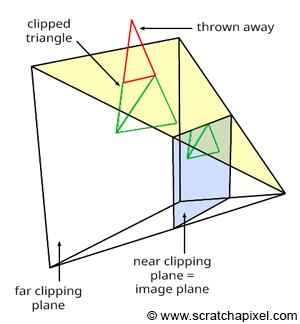
You also need to know that it is when the vertex is in clip space that the GPU decides whether to keep or discard the vertex. This process is a bit more complex because vertices are connected to one another to form triangles, and vertices making up a triangle can straddle the clipping volume boundaries. This is why we speak of clipping rather than culling. If all three vertices making up a triangle are contained within the clip space, we keep the triangle. If all vertices are outside of the clipping volume, we can cull the triangle. If at least one of the triangle's vertices straddles that volume, then we need to clip the triangle to the volume itself, leading to the generation of new triangles. That's what clipping is all about.
Then, once clipped, the triangle's vertices undergo the perspective divide, a process performed by the GPU. This involves converting the vertices—at this point defined in homogeneous coordinates—back to Cartesian coordinates. The vertices transition from clip space \(\rightarrow\) Normalized Device Coordinate space (NDC), where their x, y, and z coordinates are all contained within the range \([-1, 1]\).
How Does the GPU Do It (So Fast)?
The reason why GPUs are superior to CPUs for these kinds of operations is that GPUs are made up of what we call Streaming Multiprocessors (SMs)—say 72 per card (these are orders of magnitude for cards built in the late 2010s/early 2020s)—which themselves consist of what we call ALUs (say 64 per SM), short for Arithmetic Logic Units. Note that there can be many of these SMs on a single GPU, each grouped into multiple Graphics Processing Clusters or GPCs (e.g., 6 GPCs, each containing 12 SMs). So let's recap: you have multiple GPCs on a GPU (x6), each containing many SMs (x12), all of which contain many ALUs (x64). This makes in our example a total of 4608 cores (called CUDA cores in Nvidia's terminology). You also have ALUs on CPUs, but not in as great a number as on GPUs. It's because GPUs have thousands of these units, each capable of processing operations simultaneously, that GPUs can process vertices in parallel batches, hence processing them faster than a CPU would. Many operations in the graphics pipeline (assuming rasterization here, though some of the same logic also applies to ray tracing) can easily be applied to data units such as vertices, independently of other vertices. So the pipeline can take batches of vertices at a time and process them in parallel. This is true of the vertex shader, which can be applied to vertices independently.
Clipping and rasterization can take place on dedicated hardware specialized for that process (called the raster engine), but the rest of the pipeline, such as the perspective divide and shading individual fragments (fragments are the result of the rasterization process and can be seen as a kind of pre-form of pixels), can also be processed in parallel by these multiple SMs, which themselves contain a great number of ALUs capable of running operations in parallel.
You now have a better understanding of why GPUs are good at rendering images of 3D scenes. Essentially, it's because they've been designed to parallelize all the steps in the graphics pipeline that can be parallelized and to provide enough transistors to effectively do these things in parallel, with the perspective projection matrix playing a key role in that process. The following video provides a fun illustration of that concept.
So in short, GPUs have more "cores" in a way than a CPU (though they usually run at a lower clock speed) and have other specialized hardware for applying some steps of the graphics pipeline, such as rasterization.