The Perspective Projection Matrix
Reading time: 22 mins.The OpenGL Perspective Projection Matrix
In all OpenGL books and references, the perspective projection matrix used in OpenGL is defined as:
$$ \left[\begin{array}{cccc} \frac{2n}{r-l} & 0 & \frac{r + l}{r-l} & 0 \\ 0 & \frac{2n}{t-b} & \frac{t + b}{t-b} & 0 \\ 0 & 0 & -\frac{f+n}{f-n} & -\frac{2fn}{f-n}\\ 0 & 0 & -1 & 0\\ \end{array}\right] $$What similarities does this matrix have with the matrix we studied in the previous chapter? It is important to remember that matrices in OpenGL are defined using a column-major order, as opposed to row-major order. In the lesson on Geometry, we explained that to transition from one order to the other, one can simply transpose the matrix. If we transpose the above matrix, we get:
$$ \left[\begin{array}{cccc} \frac{2n}{r-l} & 0 & 0 & 0 \\ 0 & \frac{2n}{t-b} & 0 & 0 \\ \frac{r + l}{r-l} & \frac{t + b}{t-b} & -\frac{f+n}{f-n} & {\color{red}{-1}}\\ 0 & 0 & -\frac{2fn}{f-n} & 0\\ \end{array}\right] $$This is the matrix we would use on Scratchapixel, as we use row vectors. However, in OpenGL, you would use the first matrix, as OpenGL uses column vectors by default, though this can be changed in OpenGL 4.x and modern real-time 3D graphics APIs such as Vulkan. Pay attention to the element in red (third row and fourth column). When we multiply a homogeneous point with this matrix, the point's \(w\) coordinate is multiplied by this element, and the value of \(w\) ends up being the projected point's \(z\) coordinate:
$$ \left[\begin{array}{cccc}x' & y' & z' & w'\end{array}\right] = \left[\begin{array}{cccc}x & y & z & w = 1\end{array}\right] * \left[\begin{array}{cccc} \frac{2n}{r-l} & 0 & 0 & 0 \\ 0 & \frac{2n}{t-b} & 0 & 0 \\ \frac{r + l}{r-l} & \frac{t + b}{t-b} & -\frac{f+n}{f-n} & {\color{red}{-1}}\\ 0 & 0 & -\frac{2fn}{f-n} & 0\\ \end{array}\right] $$ $$P'_w = 0 \cdot P_x + 0 \cdot P_y - 1 \cdot P_z + 0 = -P_z.$$Our mathematical expressions and equations are accurate, reflecting the correct formulas for the perspective projection matrix as used in OpenGL and its transformation upon transposition.
Principle
In summary, we understand that the matrix is correctly set up for the z-divide. Let's now examine how points are projected in OpenGL (Vulkan, Meta, Direct3D or WebGL). The principle remains the same as discussed in the previous chapter. A line is drawn from the camera's origin to the point \(P\) that we want to project, and the intersection of this line with the image plane determines the position of the projected point \(P_s\). While the setup mirrors that shown in figure 1 from the previous chapter, it's important to note that in OpenGL, the image plane is situated on the near clipping plane, as opposed to being precisely one unit away from the camera's origin.

The technique of using similar triangles, as employed in chapter 1, is applicable here as well. The triangles \(\Delta ABC\) and \(\Delta DEF\) are similar. Thus, we can express:
$$\frac{AB}{DE} = \frac{BC}{EF}.$$By substituting \(AB\) with \(n\) (the near clipping plane), \(DE\) with \(P_z\) (the z-coordinate of \(P\)), and \(EF\) with \(P_y\) (the y-coordinate of \(P\)), we can rewrite this equation as (equation 1):
$$\frac{n}{-P_z} = \frac{BC}{P_y} \rightarrow BC = P_s{}_y = \frac{n \cdot P_y}{-P_z}.$$As observed, the only difference from the equation in the previous chapter is the inclusion of \(n\) in the numerator. However, the principle of division by \(P_z\) remains unchanged (noting that since the camera is oriented along the negative z-axis, \(P_z\) is negative: \(P_z < 0\)). To maintain the y-coordinate of the projected point as positive, given that \(P_y\) is positive, we negate \(P_z\). Following the same logic, we derive the x-coordinate of the projected point with the following equation (equation 2):
$$P_s{}_x = \frac{n \cdot P_x}{-P_z}.$$Derivation
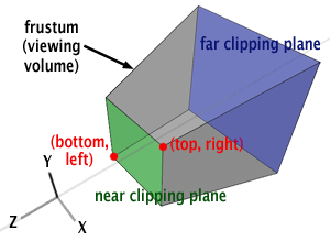
Having determined the values for \(P_s{}_x\) and \(P_s{}_y\), we now need to elucidate how they correlate with the OpenGL perspective matrix. The purpose of a projection matrix is to remap the values projected onto the image plane to a unit cube (defined by minimum and maximum extents of \((-1,-1,-1)\) and \((1,1,1)\), respectively). Once the point \(P\) is projected onto the image plane, \(P_s\) is considered visible if its \(x\) and \(y\) coordinates fall within the range \([left, right]\) for \(x\) and \([bottom, top]\) for \(y\), as depicted in Figure 2. While we have previously discussed in the lesson 3D Viewing: the Pinhole Camera Model how the \(left\), \(right\), \(bottom\), and \(top\) coordinates are calculated, we will revisit this explanation in this chapter. These screen coordinates set the limits or boundaries on the image plane for visible points (all points contained in the viewing frustum and projected onto the image plane). Assuming \(P_s{}_x\) is visible, it can be expressed as:
$$l \leq P_s{}_x \leq r,$$where \(l\) and \(r\) represent the left and right coordinates, respectively. Our objective is to remap \(P_s{}_x\) so that its final value resides within the range \([-1,1]\) (the dimensions of the unit cube along the \(x\)-axis). Reiterating the equations introduced in the previous lesson, let's start by subtracting \(l\) from all terms to rewrite the equation as:
$$0 \leq P_s{}_x - l \leq r - l.$$Normalizing the term on the right by dividing all terms of this formula by \(r-l\) yields:
$$0 \leq \frac{P_s{}_x - l}{r-l} \leq 1.$$Multiplying all terms by 2 gives:
$$0 \leq 2\frac{P_s{}_x - l}{r-l} \leq 2.$$Subtracting 1 from all terms results in:
$$-1 \leq 2\frac{P_s{}_x - l}{r-l} - 1 \leq 1.$$This remaps the central term to the range \([-1,1]\), which was our goal, though the terms can be further rearranged:
$$-1 \leq 2 \frac{P_s{}_x - l}{r-l} - \frac{r-l}{r-l} \leq 1.$$Developing this, we obtain:
$$-1 \leq \frac{2P_s{}_x - 2l - r + l}{r-l} \leq 1.$$Therefore:
$$-1 \leq \frac{2P_s{}_x - l - r}{r-l} \leq 1 \rightarrow -1 \leq \frac{2P_s{}_x}{r-l} - \frac{r + l}{r - l} \leq 1.$$These two terms are quite similar to the first two terms of the first row in the OpenGL perspective projection matrix. We are getting closer. If we replace \(Ps_x\) from the previous equation with equation 2, we get:
$$-1 \leq \dfrac{2n P_x}{-P_z(r-l)} - \dfrac{r + l}{r - l} \leq 1.$$We can easily encode this equation in matrix form. If we replace the first and third coefficients of the matrix's first row with the first and second term of this formula, here is what we get:
$$ \left[\begin{array}{cccc} \dfrac{2n}{r-l} & 0 & \dfrac{r + l}{r-l} & 0 \\ \ldots & \ldots & \ldots & \ldots \\ \ldots & \ldots & \ldots & \ldots \\ 0 & 0 & -1 & 0\\ \end{array}\right] $$Remember, the OpenGL matrix uses column-major ordering, therefore, we will have to place the multiplication sign to the right of the matrix and the point coordinates in a column vector:
$$ \left[\begin{array}{cccc} \dfrac{2n}{r-l} & 0 & \dfrac{r + l}{r-l} & 0 \\ \ldots & \ldots & \ldots & \ldots \\ \ldots & \ldots & \ldots & \ldots \\ 0 & 0 & -1 & 0\\ \end{array}\right] * \left[ \begin{array}{c}x \\ y \\ z \\ w\end{array}\right] $$Computing \(Ps_x\) using this matrix yields:
$$Ps_x = \dfrac{2n}{r-l} P_x + 0 \cdot P_y + \dfrac{r + l}{r-l} \cdot P_z + 0 \cdot P_w.$$You should be familiar with the concept of matrix-vector multiplication at this point, as well as the concept of row versus column-major vectors and matrices. In this particular example, we use column-major vector notation (that's the convention used by OpenGL, not by Scratchapixel—we prefer the row-major notation) to compute the transformed coordinate of the first coordinate (x) you need to use the coefficients of the matrix's first row and the vector's coordinates in the following way:
$$Px_{transform} = M_{00} \cdot Px + M_{01} \cdot Py + M_{02} \cdot Pz + M_{03} \cdot Pw.$$If you are not familiar with these concepts, read the lesson on Geometry.
And since \(Ps_x\) will be divided at the end of the process by \(-P_z\) when we convert \(Ps\) from homogeneous to Cartesian coordinates, we get:
$$ Ps_x = \frac{\frac{2n}{r-l} P_x}{-P_z} + \frac{\frac{r + l}{r-l} P_z}{-P_z} \rightarrow \frac{2n P_x}{-P_z(r-l)} - \frac{r + l}{r-l}. $$This is the first coordinate of the projected point \(Ps\) computed using the OpenGL perspective matrix. The derivation is quite lengthy, and we will skip it for \(Ps_y\). However, if you follow the steps we used for \(Ps_x\), doing it yourself shouldn't be a problem. You just need to replace \(l\) and \(r\) with \(b\) and \(t\), and you end up with the following formula:
$$-1 \leq \frac{2n P_y}{-P_z(t-b)} - \frac{t + b}{t - b} \leq 1.$$We can achieve this result with point-matrix multiplication if we replace the second and third coefficients of the matrix's second row with the first and second terms of this equation:
$$ \left[\begin{array}{cccc} \frac{2n}{r-l} & 0 & \frac{r + l}{r-l} & 0 \\ 0 & \frac{2n}{t-b} & \frac{t + b}{t-b} & 0 \\ \ldots & \ldots & \ldots & \ldots \\ 0 & 0 & -1 & 0\\ \end{array}\right] $$Computing \(Ps_y\) using this matrix gives:
$$Ps_y = 0 \cdot P_x + \frac{2n}{t-b} \cdot P_y + \frac{t + b}{t-b} \cdot P_z + 0 \cdot P_w$$and after the division by \(-P_z\):
$$Ps_y = \frac{\frac{2n}{t-b} P_y}{-P_z} + \frac{\frac{t + b}{t-b} P_z}{-P_z} \rightarrow \frac{2n P_y}{-P_z(t-b)} - \frac{t + b}{t-b}$$Our matrix works again. All that's left to do to complete it is find a way to remap the z-coordinate of the projected points to the range [-1,1]. We know that the x- and y-coordinates of \(P\) don't contribute to the calculation of the projected point's z-coordinate. Thus, the first and second coefficients of the matrix's third row, which would be multiplied by \(P\)'s x- and y-coordinates, are necessarily zero (in green). We are left with two coefficients, \(A\) and \(B\), in the matrix which are unknown (in red).
$$ \left[\begin{array}{cccc} \frac{2n}{r-l} & 0 & \frac{r + l}{r-l} & 0 \\ 0 & \frac{2n}{t-b} & \frac{t + b}{t-b} & 0 \\ \color{green}{0} & \color{green}{0} & \color{red}{A} & \color{red}{B}\\ 0 & 0 & -1 & 0 \\ \end{array}\right] $$If we write the equation to compute \(Ps_z\) using this matrix, we get (remember that \(Ps_z\) is also divided by \(Ps_w\) when the point is converted from homogeneous to Cartesian coordinates, and that \(P_w = 1\)):
$$ Ps_z = \frac{0 \cdot P_x + 0 \cdot P_y + A \cdot P_z + B \cdot P_w}{Ps_w = -P_z} \rightarrow \frac{A \cdot P_z + B}{Ps_w = -P_z}. $$We need to find the values of A and B. Fortunately, we know that when \(P_z\) is on the near clipping plane, \(Ps_z\) needs to be remapped to -1, and when \(P_z\) is on the far clipping plane, \(Ps_z\) needs to be remapped to 1. Therefore, we need to replace \(Ps_z\) with \(n\) and \(f\) in the equation to get two new equations (note that the z-coordinate of all the points projected on the image plane is negative, but \(n\) and \(f\) are positive, therefore we will use \(-n\) and \(-f\) instead):
$$ \left\{ \begin{array}{ll} \frac{(P_z=-n)A + B}{(-P_z=-(-n)=n)} = -1 & \text{ when } P_z = n\\ \frac{(P_z=-f)A + B}{(P_z=-(-f)=f)} = 1 & \text{ when } P_z = f \end{array} \right. \\ \rightarrow \left\{ \begin{array}{ll} {-nA + B} = -n & (1)\\ {-fA + B} = f & (2) \end{array} \right. $$Let's solve for B in equation 1:
$$B = -n + An.$$And substitute B in equation 2 with this equation:
$$-fA - n + An = f.$$Then solve for A:
$$-fA + An = f + n \rightarrow -(f - n)A = f + n \rightarrow A = -\frac{f + n}{f - n}.$$Now that we have a solution for A, finding B is straightforward. We just replace A in equation 1 to find B:
$$B = -n + An = -n -\frac{f + n}{f - n} n = \\-(1+\frac{f + n}{f - n}) n = - \frac{{(f -n + f + n)}n}{f - n}=-\frac { 2fn }{f -n}.$$We can replace the solutions we found for A and B in our matrix, and we finally get:
$$\left[\begin{array}{cccc} \frac{2n}{r-l} & 0 & \frac{r + l}{r-l} & 0 \\ 0 & \frac{2n}{t-b} & \frac{t + b}{t-b} & 0 \\ 0 & 0 & -\frac{f+n}{f-n} & -\frac{2fn}{f-n}\\ 0 & 0 & -1 & 0\\ \end{array}\right]$$which is the OpenGL perspective projection matrix.
Should Z be in Range \([-1,1]\) or \([0,1]\)? This Sadly Matters
Whether Z should be in the range \([-1,1]\) or \([0,1]\) is a valid question. So far, we've chosen to remap \(z\) to the range \([-1,1]\) and have provided the equations for that. Most perspective matrix code remaps Z to that range. However, many (if not most) real-time graphics APIs, such as OpenGL and Vulkan, expect the depth range to be within \([0,1]\). Technically, these graphics APIs allow you to define this range more or less as you like when you create your graphics pipeline. In Vulkan, you set minDepth and maxDepth in the VkPipelineViewportStateCreateInfo structure (which itself has a pViewports parameter where you set these depth bounds). In OpenGL, these values are set through glDepthRange.
Now, you can achieve this in two ways. You can modify the original perspective projection matrix so that the Z-coordinate directly remaps to \([0,1]\).
$$ \left\{ \begin{array}{ll} \frac{(P_z = -n)A + B}{(-P_z = -(-n) = n)} = 0 & \text{ when } P_z = n \\ \frac{(P_z = -f)A + B}{(P_z = -(-f) = f)} = 1 & \text{ when } P_z = f \end{array} \right. $$ $$ \rightarrow \left\{ \begin{array}{ll} {-nA + B} = 0 & (1) \\ {-fA + B} = f & (2) \end{array} \right. $$From which we can derive:
$$ A = -\frac{f}{f-n} $$And:
$$ B = -\frac{fn}{f-n} $$Another solution simply consists of using the original matrix and letting the real-time graphics API remap these values for you. This is possible in OpenGL because when points are transformed from NDC space to window space (or raster space, if you prefer), the \(z\) is remapped as follows:
$$ \begin{pmatrix} x_w \\ y_w \\ z_w \\ \end{pmatrix} = \begin{pmatrix} \frac{P_x}{2} x_d + o_x \\ \frac{P_y}{2} y_d + o_y \\ \frac{f \cdot n}{2} z_d + \frac{n + f}{2} \end{pmatrix} $$Don't worry too much about \(x_w\) and \(y_w\) here. We are only interested in \(z_w\) (by the way, \(w\) stands for window space here). In OpenGL, at this particular stage, the variables \(n\) and \(f\) are set to the minDepth and maxDepth values that we spoke about earlier. So if those are 0 and 1 respectively, this is similar to \(\frac{1}{2} z_d + \frac{1}{2}\), which effectively remaps points in the range \([-1,1]\) to the range \([0,1]\).
Things get a little more complicated in APIs such as Vulkan. XX
Depth Buffer Precision Issues

The remapping of the z-coordinate uniquely prioritizes points closer to the camera with greater numerical precision compared to points further away. As discussed in the previous chapter, this characteristic can lead to issues where the lack of numerical precision results in adjacent samples receiving identical depth values after projection onto the screen, despite having distinct z-coordinates in world space. This phenomenon, known as z-fighting, poses a challenge. Although the problem cannot be entirely eliminated—given the inherent limitations of precision in single-precision floating-point numbers—it can be mitigated by carefully adjusting the near and far clipping planes to align as closely as possible with the nearest and furthest objects visible in the scene. This rationale underlines the importance of precise clipping plane adjustments.

The Field of View and Image Aspect Ratio
You may have noticed that, so far, we haven't made any reference to the camera's field of view (FOV) and image aspect ratio. However, as mentioned in the previous chapter and the lesson on cameras (in the basic section), changing the FOV alters the extent of the scene viewed through the camera. Thus, the field of view and the image aspect ratio are somehow related to the projection process. We deliberately ignored this detail until now to stay focused on the OpenGL perspective projection matrix, which doesn't directly depend on the camera's field of view, but it does so indirectly. The construction of the matrix relies on six parameters: the left, right, bottom, and top coordinates, as well as the near and far clipping planes. The user provides the values for the near and far clipping planes, but how about the left, right, bottom, and top coordinates? What are these, where do they come from, and how do we calculate them? Observing Figures 2 and 5, you can see that these coordinates correspond to the lower-left and upper-right corners of the frustum front face, where the image of the 3D scene is projected.
Computing the Coordinates

To compute the top coordinate, we look at the right-angled triangle ABC. The angle subtended by AB and AC is half the FOV, and the adjacent side of the triangle is the value for the near-clipping plane. Using trigonometry, we can express this as:
$$\tan\left( \frac{ FOVY } {2}\right) = \frac{ opposite } { adjacent } = \frac {BC}{AB} = \frac{top}{near}$$Therefore:
$$ top = \tan\left( \frac{ FOVY } {2}\right) * near $$And since the bottom half of the camera is symmetrical to the upper half, we can state that:
$$bottom = -top$$The angle of view can either be defined vertically or horizontally. OpenGL tends to define the field-of-view as vertical (hence the Y in FOVY), but on Scratchapixel, we use a horizontal angle-of-view, similar to Maya and RenderMan.
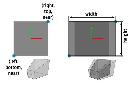
In Figure 5, two scenarios are considered: the image can either be square or rectangular. For a square camera, it's straightforward: the left and bottom coordinates are the same, the right and top coordinates are also the same, and mirroring the bottom-left coordinates around the x- and y-axis gives the top-right coordinates. Therefore, if we compute the top coordinates, we can easily set the other three:
$$ \begin{array}{l} top = \tan( \frac{ FOV } {2}) * near \\ right = top \\ left = bottom = -top \end{array} $$For a non-square camera, as shown in the right inside of figure 5, computing the coordinates becomes slightly more complicated. The bottom and top coordinates remain the same, but the left and right coordinates are scaled by the aspect ratio, defined as the image width over the image height. The general formulas for computing the left, right, and bottom coordinates are:
$$ \begin{array}{l} aspect\;ratio = \frac{width}{height}\\ top = \tan( \frac{ FOV } {2}) * near \\ bottom = -top \\ right = top * aspect\;ratio\\ left = bottom = -top * aspect\;ratio \end{array} $$Thus, the camera's field of view and image aspect ratio are crucial in calculating the left, right, bottom, and top coordinates, which in turn are used in constructing the perspective projection matrix. This is how they indirectly influence how much of the scene is visible through the camera.
Test Program
To test the OpenGL perspective projection matrix, we will reuse the code from the previous chapter. In the old fixed-function rendering pipeline, two functions, gluPerspective (part of the GLU library) and glFrustum, were utilized to set the screen coordinates and the projection matrix. These functions are deprecated (since OpenGL 3.1) in the new programmable rendering pipeline, but we use them in this lesson to demonstrate their implementation based on what we have learned in this chapter. You can still emulate them in your CPU program if desired.
Setting up the perspective projection matrix in OpenGL was achieved through a call to glFrustum. This function accepted six arguments:
glFrustum(float left, float right, float bottom, float top, float near, float far);
The implementation of this function is shown below (line 20). The function gluPerspective was used to set the screen coordinates, taking as arguments the angle of view, the image aspect ratio (image width over image height), and the clipping planes.
void gluPerspective(float fovy, float aspect, float zNear, float zFar);
In OpenGL, the angle of view is defined as the vertical angle (hence the 'y' in the variable name). On Scratchapixel, we use the horizontal angle of view. An implementation of this function is provided below (line 8). The rest of the code remains unchanged. We first compute the screen coordinates, then the projection matrix. Next, we iterate over all the vertices of the teapot geometry, transform them from object/world space to camera space, and finally project them onto the screen using the perspective projection matrix. Remember, the matrix remaps the projected point to NDC space. Thus, as in the previous version of the code, visible points fall within the range [-1,1] in height and [-imageAspectRatio, imageAspectRatio] (or [-1,1] if the image is square) in width.
#include <cstdio>
#include <cstdlib>
#include <fstream>
#include "geometry.h"
#include "vertexdata.h"

// Compute screen coordinates first
void gluPerspective(
    const float &angleOfView,
    const float &imageAspectRatio,
    const float &n, const float &f,
    float &b, float &t, float &l, float &r)
{
    float scale = tan(angleOfView * 0.5 * M_PI / 180) * n;
    r = imageAspectRatio * scale, l = -r;
    t = scale, b = -t;
}

// Set the OpenGL perspective projection matrix
void glFrustum(
    const float &b, const float &t, const float &l, const float &r,
    const float &n, const float &f,
    Matrix44f &M)
{
    // Set OpenGL perspective projection matrix
    M[0][0] = 2 * n / (r - l);
    M[0][1] = 0;
    M[0][2] = 0;
    M[0][3] = 0;

    M[1][0] = 0;
    M[1][1] = 2 * n / (t - b);
    M[1][2] = 0;
    M[1][3] = 0;

    M[2][0] = (r + l) / (r - l);
    M[2][1] = (t + b) / (t - b);
    M[2][2] = -(f + n) / (f - n);
    M[2][3] = -1;

    M[3][0] = 0;
    M[3][1] = 0;
    M[3][2] = -2 * f * n / (f - n);
    M[3][3] = 0;
}

void multPointMatrix(const Vec3f &in, Vec3f &out, the Matrix44f &M)
{
    // out = in * Mproj;
    out.x   = in.x * M[0][0] + in.y * M[1][0] + in.z * M[2][0] + M[3][0]; // in.z = 1 assumed
    out.y   = in.x * M[0][1] + in.y * M[1][1] + in.z * M[2][1] + M[3][1];
    out.z   = in.x * M[0][2] + in.y * M[1][2] + in.z * M[2][2]

 + M[3][2];
    float w = in.x * M[0][3] + in.y * M[1][3] + in.z * M[2][3] + M[3][3];

    // Normalize if w is different than 1 (convert from homogeneous to Cartesian coordinates)
    if (w != 1) {
        out.x /= w;
        out.y /= w;
        out.z /= w;
    }
}

int main(int argc, char **argv)
{
    uint32_t imageWidth = 512, imageHeight = 512;
    Matrix44f Mproj;
    Matrix44f worldToCamera;
    worldToCamera[3][1] = -10;
    worldToCamera[3][2] = -20;
    float angleOfView = 90;
    float near = 0.1;
    float far = 100;
    float imageAspectRatio = imageWidth / (float)imageHeight;
    float b, t, l, r;
    gluPerspective(angleOfView, imageAspectRatio, near, far, b, t, l, r);
    glFrustum(b, t, l, r, near, far, Mproj);
    unsigned char *buffer = new unsigned char[imageWidth * imageHeight];
    memset(buffer, 0x0, imageWidth * imageHeight);
    for (uint32_t i = 0; i < numVertices; ++i) {
        Vec3f vertCamera, projectedVert;
        multPointMatrix(vertices[i], vertCamera, worldToCamera);
        multPointMatrix(vertCamera, projectedVert, Mproj);
        if (projectedVert.x < -imageAspectRatio || projectedVert.x > imageAspectRatio || projectedVert.y < -1 || projectedVert.y > 1) continue;
        // Convert to raster space and mark the vertex position on the image with a simple dot
        uint32_t x = std::min(imageWidth - 1, (uint32_t)((projectedVert.x + 1) * 0.5 * imageWidth));
        uint32_t y = std::min(imageHeight - 1, (uint32_t)((1 - (projectedVert.y + 1) * 0.5) * imageHeight));
        buffer[y * imageWidth + x] = 255;
    }
    // Export to image
    std::ofstream ofs;
    ofs.open("./out.ppm");
    ofs << "P5\n" << imageWidth << " " << imageHeight << "\n255\n";
    ofs.write((char*)buffer, imageWidth * imageHeight);
    ofs.close();
    delete [] buffer;

    return 0;
}
We noted in the first chapter that even if matrices are constructed differently (and appear different), they should always yield the same result: a point in 3D space should be projected to the same pixel location on the image. Comparing the results of projecting the teapot's vertices using the first matrix with those using the same camera settings (same field of view, image aspect ratio, near and far clipping planes) and the OpenGL perspective projection matrix produces identical images (see image below).

The source code of this program is available on Scratchapixel's GitHub repo.