Geometry of a Triangle
Reading time: 9 mins.Basic Mathematical Tools
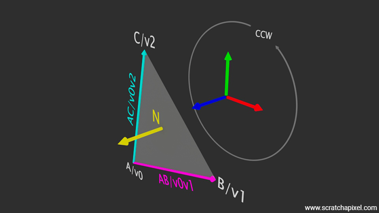
Before exploring the techniques to solve the ray-triangle intersection test, it's essential to familiarize ourselves with some foundational mathematical tools. As previously mentioned, a triangle's vertices define a plane. Each plane is characterized by a normal, which is a vector perpendicular to the plane's surface. Given the coordinates of the triangle's vertices \(A\), \(B\), and \(C\), we can compute vectors \(AB\) and \(AC\), which represent the edges from \(A\) to \(B\) and from \(A\) to \(C\), respectively. This is accomplished by subtracting \(B\) from \(A\) and \(C\) from \(A\).
A note here: Remember that Scratchapixel uses a right-hand coordinate system in all its lessons (with the up vector being the y-axis). Therefore, when you look at a triangle from the front, the triangle's vertices will be labeled \(v0\), \(v1\), and \(v2\) in a counter-clockwise fashion.
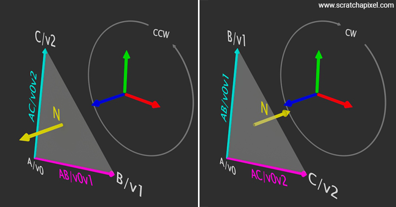
Similarly, it is logical to define the first vertex, from which subsequent vectors such as \(AB\) or \(AC\) will be calculated, as \(A\) or v0. However, choosing \(A\) over \(B\) or \(C\) is purely arbitrary. All the math we are about to provide will work exactly the same if you decide to start from vertex \(B\) or \(C\) (as shown in the figure below), though this may not seem like something you would typically do.
When we get to the lesson on Barycentric Coordinates, you will see that it might be convenient to consider a starting point other than \(A\). The only requirement, if you do so, is to ensure that you "walk" around the triangle in a counter-clockwise manner. For example, if you choose \(C\) as your starting vertex, the next vertex should be \(A\), followed by \(B\).
For now, and for the purposes of this chapter and the next, we will assume \(A\) or v0 as the first vertex from which subsequent vectors will be defined. However, keep in mind that this is not a strict requirement for the math to work.

In the image above, we've represented all three possible options for calculating the normal vector, each time choosing the magenta-colored vector as the first vector in the cross-product calculation, and of course, the cyan-colored vector as the second. This highlights that it is not necessary to always consider the vertex \( A \) (or \( v_0 \)) as the first vertex from which to calculate all subsequent variables. You can choose either \( B \) or \( C \) as the starting point, as long as you always consider your vertices in a counterclockwise manner (a possible mathematical term for this is cyclic permutation).
To determine the plane's normal—which also serves as the triangle's normal, as the triangle resides within the plane—we calculate the cross product of vectors \(AB\) and \(AC\). Since these vectors lie in the same plane (connecting the triangle's vertices), the resulting vector from the cross product, denoted as \(N\), represents the sought-after normal (see Figure 1). The operations are summarized in the following pseudocode:
Vec3f v0(-1, -1, 0), v1(1, -1, 0), v2(0, 1, 0);
Vec3f e0 = v1 - v0; // Edge 0
Vec3f e1 = v2 - v0; // Edge 1
Vec3f N = cross(e0, e1); // Triangle's normal
normalize(N);
The mathematical representation of these operations is as follows:
$$ \begin{array}{l} AB = B - A = (1 - (-1), -1 - (-1), 0 - 0) = (2, 0, 0) \\ AC = C - A = (0 - (-1), 1 - (-1), 0 - 0) = (1, 2, 0) \\ N = AB \times AC \\ N_x = AB_y \cdot AC_z - AB_z \cdot AC_y = 0 \cdot 0 - 0 \cdot 2 = 0 \\ N_y = AB_z \cdot AC_x - AB_x \cdot AC_z = 0 \cdot 1 - 2 \cdot 0 = 0 \\ N_z = AB_x \cdot AC_y - AB_y \cdot AC_x = 2 \cdot 2 - 0 \cdot 1 = 4 \\ \end{array} $$After normalizing \(N\), we obtain the vector \((0, 0, 1)\), which is parallel to the positive \(z\)-axis. This outcome is expected, given that the vertices \(A/v0\), \(B/v1\), and \(C/v2\) are positioned in the \(XY\)-plane.
Coordinate System Handedness
The order in which a triangle's vertices are defined significantly affects the orientation of the surface normal. Defining vertices \(v_0\), \(v_1\), and \(v_2\) in a counter-clockwise (CCW) order results in a normal denoted by \(N\). Conversely, if the vertices are defined in a clockwise (CW) order, the normal obtained from the cross product of the two edges (\(v0v1 = v_1 - v_0\) and \(v0v2 = v_2 - v_0\)) points in the opposite direction, yielding \(-N\). Similarly, if you compute \(v0v2 \times v0v1\) instead of \(v0v1 \times v0v2\), you would also get \(-N\). Therefore, be sure to use \(v0v1 \times v0v2\) when working with counter-clockwise ordered vertices, as expected when using a right-hand coordinate system.
When creating a triangle in Maya, which uses a right-hand coordinate system, generating the triangle's vertices in a counter-clockwise (CCW) order implies that, if you create a triangle in the XY plane and take the cross product of the vectors defined by \(v0v1\) and \(v0v2\), the resulting vector (the triangle's normal) will point in the same direction as the world coordinate system's positive z-axis (Figure 2). However, if the vertices are created in a clockwise order, then \(N\) will point along the negative z-axis. Creating vertices in a clockwise order and computing \(N\) from the cross product \(v0v1 \times v0v2\) is equivalent to computing the cross product \(v0v2 \times v0v1\) when vertices are created in a counter-clockwise order. (I know I have just said this above already, but I will leave that repetition just in case this explanation makes more sense than the previous one.)
Imagine creating this triangle in a left-hand coordinate system (unlike the right-hand coordinate system used in the examples above and assumed throughout all of Scratchapixel's lessons), using the same vertex coordinates as in the right-hand coordinate system example (\(v_0 = (0,0,0)\), \(v_1=(1,0,0)\), and \(v_2=(0,1,0)\)). Following the same steps, we create vectors \(v0v1\) (\(v_1-v_0\)) and \(v0v2\) (\(v_2-v_0\)), and compute \(N\) (from \(v0v1 \times v0v2\)). The result is \((0,0,1)\), identical to the right-hand coordinate system example, as the vertices' coordinates are the same. Hence, vectors \(v0v1\) and \(v0v2\), as well as the cross product \(v0v1 \times v0v2\), remain unchanged. By convention, the z-axis in the left-hand coordinate system points away from the screen (when the x-axis points to the right, with the y-axis pointing up), aligning with our explanation of the handedness of coordinate systems. The cross product is an anti-commutative operation, as discussed in our lesson on Geometry.
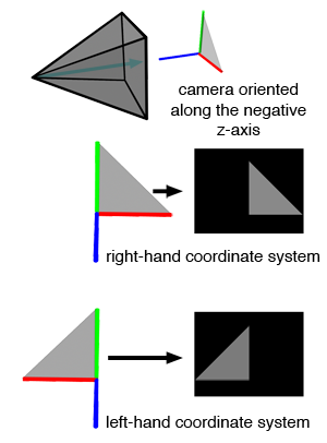
The next step is to render these triangles from a camera facing down the negative z-axis. The results, shown in Figure 4, demonstrate that the two images look different, even though the triangles have the same vertex coordinates. This discrepancy is a problem because changing the handedness of the coordinate system should not change how the triangle looks from the camera. Ideally, regardless of which handedness is used, the triangle should appear the same. Although this issue isn’t directly related to ray-triangle intersection tests, it is still an important consideration. We can fix this by flipping the camera along the negative z-axis, including both its position and direction, as shown in Figure 4.
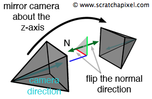
However, this adjustment changes the direction of both the camera and the triangle's normal compared to their original orientation before the mirroring. In Figure 3, the camera and the triangle's normal point in opposite directions. After the adjustment, they point in the same direction. These two vectors—the triangle's normal and the camera direction—are important for shading, so their relative positions should stay the same.
So the solution for the flipped triangle issue would be to mirror the camera and reverse the triangle's normal. However, this requires keeping track of which geometry was modeled in a coordinate system with a different handedness than the rendering program, meaning we would need to reverse the normal for that geometry during the shading stage. This approach is not ideal.
For example, if a triangle is defined with vertices \(v_0\), \(v_1\), and \(v_2\) in a left-hand coordinate system, when converting to a right-hand coordinate system, you should negate the x-coordinates and reverse the order to \(v_2\), \(v_1\), and \(v_0\).
This adjustment is only necessary when geometry is created in one coordinate system but rendered in another, such as creating geometry in Maya (which uses a right-hand system) and rendering it in RenderMan (which uses a left-hand system). Once these changes are made, there is no need to modify the camera setup or negate the normal during shading. The model will visually appear the same, with the normal pointing outward as expected, regardless of the coordinate system’s handedness used by the rendering application.
The specific order and direction in which vertices are defined is referred to as winding.
With these tools at our disposal, we are well-equipped to tackle the ray-triangle intersection test using simple geometry.