An Overview of the Rendering Process: Visibility and Shading
Reading time: 11 mins.An image of a 3D scene can be generated in multiple ways, but, of course, any method chosen should produce the same image for a given scene. In most cases, the goal of rendering is to create a photo-realistic image, although non-photorealistic rendering (NPR) is also possible. But what does "photo-realistic" mean, and how can it be achieved? Essentially, photorealism requires creating an image so "real" that it resembles a photograph, or—if photography didn't exist—it would mirror reality as our eyes perceive it, akin to the world's reflection off a mirror's surface. This is achieved by understanding and simulating the physical laws that dictate how objects appear to us. Many laws contribute to shaping our world, but only a subset directly influences its appearance. For example, gravity—a force integral to solid-body simulation—plays a minimal role in determining an orange's appearance. Thus, in rendering, our interest lies in simulating the behavior of light as it propagates through space and interacts with matter, which is fundamental to object appearance.
Perspective Projection and the Visibility Problem
First, we must understand and replicate how our eyes perceive objects, focusing not on their appearance but on their shape and size relative to their distance from the eye. The human eye is an optical system that converges light rays (reflected from objects) to a focus point.
Due to geometric construction, objects further away from our eyes appear smaller than those closer, assuming all objects are of the same size. In other words, an object's apparent size decreases as its distance from us increases. This is a direct consequence of our eyes' design. However, since we are accustomed to perceiving the world this way, it's logical to produce images with the same effect, known as the foreshortening effect. Cameras and photographic lenses were designed to replicate this phenomenon. Thus, photorealistic rendering not only simulates the physical laws of light interaction but also mimics how our visual system interprets these interactions. We aim to produce images on a flat surface that mimic the way images are formed in our eyes, primarily due to our eyes' design (the brain's processing of these images is less crucial for our purposes).
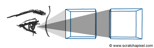
How is this accomplished? A fundamental method involves tracing lines from the corners of objects to the eye, finding where these lines intersect with an imaginary canvas—a flat surface like a sheet of paper or a screen surface—positioned perpendicular to the line of sight (see Figure 2).
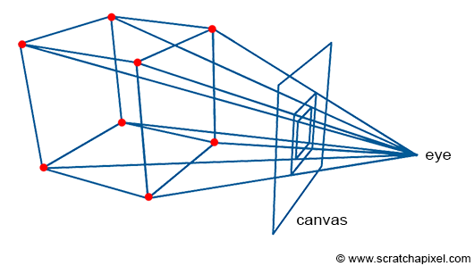
By connecting these intersection points, we can recreate the edges of the objects. The process of projecting a 3D point onto the canvas surface, as just described, is termed perspective projection. Figure 3 (not shown) would illustrate how a box appears when using this technique to "trace" its image onto a flat surface (the canvas).
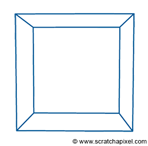
This sort of rendering in computer graphics is called a wireframe because only the edges of the objects are drawn. However, this image is not photo-realistic. If the box were opaque, the front faces of the box (at most three of these faces) should occlude or hide the rear ones, which is not the case in this image. Moreover, if more objects were in the scene, they would potentially occlude each other. Thus, one of the challenges we need to address in rendering is not only how we project the geometry onto the scene, but also how we determine which part of the geometry is visible and which part is hidden, a concept known as the visibility problem. This involves determining which surfaces and parts of surfaces are not visible from a certain viewpoint. The process is known under many names in computer graphics: hidden surface elimination, hidden surface determination (also known as hidden surface removal), occlusion culling, and visible surface determination. Why so many names? Because this was one of the first major challenges in rendering, prompting significant research in the early days of computer graphics, leading to various algorithms and thus different names.
The visibility problem can be solved in many different ways, generally falling into two main categories:
-
Rasterization
-
Ray-tracing
Rasterization might not be a common name, but for those familiar with hidden surface elimination algorithms, it includes the z-buffer and painter's algorithms, among others. Almost all graphics cards (GPUs) use an algorithm from this category, likely z-buffering. Both methods will be detailed in the next chapter.
Shading
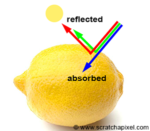
Even though we haven't detailed how the visibility problem can be solved, let's assume for now that we know how to flatten a 3D scene onto a flat surface using perspective projection and determine which part of the geometry is visible from a certain viewpoint. This is a significant step towards generating a photorealistic image, but what else do we need? Objects are not only defined by their shape but also by their appearance. This includes not just how big they appear on the scene, but in terms of their look, color, texture, and how bright they are. Furthermore, objects are only visible to the human eye because light bounces off their surface. How can we define the appearance of an object? The appearance can be defined by how the material of the object interacts with light. Light is emitted by sources (such as the sun, light bulbs, or the flame of a candle) and travels in a straight line until it contacts an object. Here, it can either be absorbed by the object or reflected into the environment. When light is reflected off an object's surface, it continues traveling (potentially in a different direction) until it either contacts another object (repeating the process) or reaches our eyes (where it is converted into electrical signals sent to the brain).
-
Absorption gives objects their unique color. White light is composed of all colors of the visible spectrum. When white light strikes an object, some colors are absorbed while others are reflected. These reflected colors mix to define the object's color. For example, under sunlight, if an object appears yellow, it means it absorbs blue light and reflects a combination of red and green light, forming yellow. A black object absorbs all light colors, while a white object reflects them all. The color of an object is unique to the material it is made of.
-
Reflection: While it's known that objects reflect light colors they don't absorb, the direction in which this light is reflected is both simple and complex. At the object level, light behaves similarly to a tennis ball bouncing off a solid surface, traveling in a direction flipped around a vector perpendicular to the surface at the point of impact. In computer graphics, this direction is called a normal: the outgoing direction is a reflection of the incoming direction with respect to the normal. At the atomic level, when a photon interacts with an atom, the photon can be absorbed or re-emitted in a new, random direction. This re-emission is known as scattering.
In computer graphics (CG), we generally won't simulate light interaction with atoms, but rather at the object level. However, this is not straightforward. If the math for computing a tennis ball's new direction after bouncing is simple, the reality is that surfaces at the microscopic level are generally not flat, causing light to bounce in almost random directions. From the distance at which we observe common objects (like a car, a pillow, or a fruit), we don't see their microscopic structure, although it significantly impacts how they reflect light and thus their appearance. Representing objects at the microscopic level is impractical due to the sheer amount of geometry required. The solution is to develop a mathematical model to simulate light interaction with materials at the microscopic level, embodied by what we call a shader in CG. A shader implements a model designed to simulate light's interaction with matter at the microscopic level.
Light Transport
Rendering is primarily about simulating the way light travels in space. Light is emitted from sources and reflects off the surfaces of objects, with some of that light eventually reaching our eyes. This is how and why we see the objects around us. As mentioned in the introduction to ray tracing, it is not very efficient to trace the path of light from a source to the eye. When a photon hits an object, the direction it will take after being reflected off the surface is unpredictable. It might travel towards the eyes, but given the small size of the eye, it is more likely to miss. While it's not impossible to simulate the transport of light as it occurs naturally (this method is called forward tracing), it is rarely done in practice due to inefficiency.
A more efficient solution is to trace the path of light in reverse, from the eye to the light source. This approach, known as backward tracing, follows the natural path of light in reverse.
The terms forward and backward tracing are sometimes interchanged in CG literature. Most renderers trace light from the eye to the emission source. Since this is the 'default' implementation in computer graphics, some people refer to it as forward tracing. However, on Scratchapixel, we will use "forward" for when light goes from the source to the eye, and "backward" for when we trace its path in reverse.
The essence of rendering lies in simulating how light propagates through space. This isn't a simple challenge, not because we lack understanding, but because simulating the true behavior of nature involves tracking so many photons that it would take an impractical amount of time to produce an image. Therefore, in practice, we trace the paths of far fewer photons to keep render times reasonable, although this means the final image won't be as accurate as it could be with a more exhaustive simulation. Finding the right balance between photorealism and render time is key to effective rendering. A light transport algorithm is designed to simulate the way light travels in space to produce an image of a 3D scene that closely matches reality.
When light bounces off a diffuse surface and illuminates surrounding objects, this effect is known as indirect diffuse. Light can also reflect off shiny objects, creating caustics (the disco ball effect). Unfortunately, devising an algorithm that can simulate all these effects simultaneously is challenging. Often, it's necessary to simulate these effects independently.
Light transport is a cornerstone of rendering and constitutes a broad field of research.
Summary
In this chapter, we've learned that rendering can essentially be seen as a two-step process:
-
The perspective projection and visibility problem on one hand,
-
And the simulation of light (light transport) as well as the simulation of the appearance of objects (shading) on the other.
Have you ever heard the term **graphics or rendering pipeline**?
The term is often used in the context of real-time rendering APIs (such as OpenGL, DirectX, or Metal). The rendering process, as explained in this chapter, can be decomposed into at least two main steps: visibility and shading. However, each of these steps can be broken down into smaller stages (which is the more common terminology). These stages are generally executed in sequential order, with the input of any given stage depending on the output of the preceding one. This sequence of stages forms what is known as the rendering pipeline.
Always keep this distinction in mind. When studying a particular technique, try to determine whether it relates to one aspect or the other. Most lessons from this section (and the advanced rendering section) fall within one of these categories.
Projection/Visibility Problem:
-
Perspective Projection Matrix
-
Rays and Cameras
-
Rendering a Triangle with Ray Tracing
-
Rendering Simple Shapes with Ray Tracing
-
Rendering a Mesh Using Ray Tracing
-
Transform Objects using Matrices
-
Rendering the Utah Teapot
-
The Rasterization Algorithm
-
...
Light Transport/Shading:
-
The Rendering Equation
-
Light Transport Algorithms: e.g., Path Tracing
-
Area Lights
-
Texturing
-
Motion Blur
-
Depth of Field
-
...
We will briefly detail both steps in the upcoming chapters.