And It Follows with a 3D Scene
Reading time: 16 mins.And It Follows With a 3D Scene
Before we delve into rendering, it's crucial to understand what we are rendering and what we are observing. Without anything to view, there is, essentially, nothing to render.
The real world is composed of objects with a vast array of shapes, appearances, and structures. Consider, for instance, the distinctions among smoke, a chair, and the water of the ocean. In computer graphics, objects are typically categorized as either solid or not. Yet, in the real world, what differentiates these states is the density of the matter composing these objects. Smoke consists of loosely connected molecules separated by significant empty space, whereas the wood in a chair comprises molecules densely packed into the smallest possible volume. In computer graphics, however, we usually only need to define the object's external shape (the rendering of non-solid objects will be addressed later in this series). How do we accomplish this?
In the preceding lesson, titled *Where Do I Start? A Gentle Introduction to Computer Graphics Programming*, we introduced the concept of defining shape within a computer's memory, starting with the fundamental concept of a point in 3D space. Generally, a point is represented as three floats in a computer's memory, one for each axis of the Cartesian coordinate system: x, y, and z. From here, we can define multiple points in space and connect them to outline a surface (a polygon). It's important to note that polygons should always be coplanar, meaning all points composing a face or polygon should lie on the same plane. With three points, you can create the simplest shape: a triangle. Triangles are ubiquitous, especially in ray-tracing, because various techniques have been developed to efficiently calculate the intersection of a line with a triangle. When faces or polygons have more than three points (also known as vertices), it's common to convert these faces into triangles, a process called triangulation.
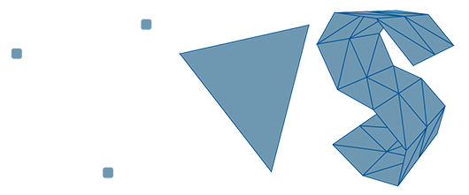
Explaining later why converting geometry to triangles is beneficial, the essence is that the triangle represents the simplest surface or object you can create. Although a single triangle might not be particularly useful, assembling multiple triangles allows for the creation of more complex shapes. In many respects, this process mirrors the act of assembling bricks to construct more intricate shapes and surfaces.
It's crucial to acknowledge that the world is not inherently polygonal; this is a simplification for the purposes of digital representation and rendering.
Most newcomers to computer graphics often wonder how curved surfaces can be constructed using triangles, given that a triangle is inherently flat and angular. Firstly, it's crucial to understand that the way we define the surface of objects in computer graphics—using triangles or polygons—is a simplified representation of reality. What might appear as a flat surface to our eyes, such as a wall, is incredibly complex at the microscopic level. The microscopic structure of objects significantly influences their appearance, not necessarily their overall shape—a fascinating aspect to keep in mind.
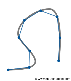
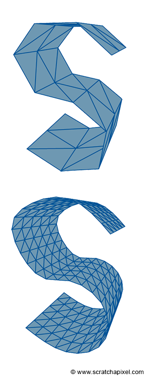
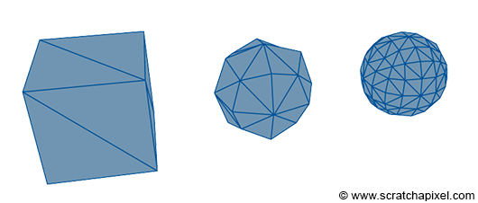
Returning to the main question, employing triangles or polygons indeed isn't the optimal method for representing curved surfaces. This approach imparts a faceted appearance to objects, somewhat akin to a cut diamond. This faceted look can be somewhat mitigated through a technique known as smooth shading, though smooth shading is merely a visual trick. We will delve into shading techniques in upcoming lessons. If you sketch a smooth curve, you can approximate this curve by placing a few points along it and connecting these points with straight lines (segments). Enhancing this approximation merely involves reducing the size of the segments, essentially creating more points along the curve. This act of placing points or vertices along a smooth surface is termed sampling, and the conversion of a smooth surface to a triangle mesh is known as tessellation. Further in this chapter, we will explore how smooth surfaces can be defined. Similarly, in 3D shapes, creating more and smaller triangles allows for a better approximation of curved surfaces. However, increasing the geometry (or triangles) inevitably extends the rendering time. Hence, the art of rendering often involves striking a balance between the geometric detail used to approximate an object's curvature and the time it takes to render this 3D model. The geometric detail incorporated into a 3D model also hinges on the proximity of the model within the image. Closer objects necessitate more detail. Managing model complexity constitutes a vast research area in computer graphics, with significant efforts directed toward finding automatic or adaptive methods for adjusting an object's triangle count based on its distance from the camera or the curvature of the object.
In essence, rendering a perfect circle or sphere using polygons or triangles is impossible. Yet, it's vital to remember that computers and monitors operate on discrete structures. There's no practical need for a renderer to perfectly render shapes like circles if they'll ultimately be displayed on a raster screen. A longstanding solution involves using triangles smaller than a pixel, rendering the primitive's triangular nature indiscernible to observers. This principle has been extensively applied in high-quality rendering software, such as Pixar's RenderMan, and has recently made its way into real-time applications via the tessellation process.
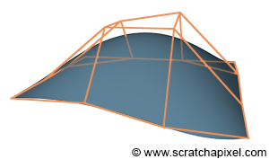
Polygonal meshes are prevalent due to their simplicity (most CG feature film or video game objects are defined this way), but they are less effective for modeling curved or organic surfaces. This became a significant issue with the advent of computer-aided design (CAD) for manufactured objects, such as cars. NURBS and Subdivision surfaces were developed to overcome this limitation. These techniques are predicated on the notion that points merely define a control mesh, from which a perfect curved surface can be mathematically computed. The surface itself, being the result of an equation, cannot be directly rendered, nor can the control mesh which merely serves as input for the algorithm. It requires sampling, akin to the earlier mentioned curve sampling process (the points forming the base or input mesh are typically called control points). One of the advantages of these techniques is the requirement for fewer points to control a perfectly smooth surface, which can then be converted into a triangular mesh smoother than the original input control mesh. While creating curved surfaces with polygons is feasible, editing them is more time-consuming and less precise compared to defining similar shapes with just a few points, as is possible with NURBS and Subdivision surfaces. If these techniques are superior, why aren't they universally adopted? They are nearly ubiquitous, slightly more costly to render than polygonal meshes because an extra step is necessary to generate a polygonal mesh from the control mesh. Hence, their use in video games is less common (though many game engines, such as Unity, Unreal Engine, Cry Engine, implement them), but they are widely used in films. NURBS are somewhat more challenging to manipulate than polygonal meshes, leading artists to prefer subdivision surfaces, though NURBS remain valuable in design and CAD for their precision. Both NURBS and Subdivision surfaces will be explored in the Geometry section. In a subsequent lesson, we will also examine Bezier curves and surfaces, which share similarities with NURBS, for rendering the iconic Utah teapot.
It's important to clarify that NURBS and Subdivision surfaces are distinct. NURBS are defined by mathematical equations and belong to the family of parametric surfaces. Conversely, Subdivision surfaces result from a process applied to the input mesh to smooth its surface through recursive subdivision. Both techniques are detailed in the Geometry section.
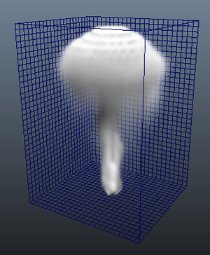
In most scenarios, 3D models are crafted manually, meaning that an individual creates vertices in 3D space and connects them to form the object's faces. However, simulation software can also be utilized to generate geometry. This approach is typically employed to create elements such as water, smoke, or fire. Specialized programs simulate fluid movement and generate a polygon mesh based on this simulation. For smoke or fire, rather than generating a surface, the program creates a 3-dimensional grid (a rectangular or cubic space divided into equally spaced cells, also known as voxels). Each grid cell represents a small volume of space, which may be empty or occupied by smoke, primarily defined by its density. Density is represented by a float, and considering a 3D grid, a 512x512x512 grid consumes approximately 512Mb of memory. This size escalates quickly, as additional data such as temperature or color might also be stored, and the memory requirement increases eightfold with each doubling of grid resolution (e.g., a 1024x1024x1024 grid requires 4Gb of storage). Fluid simulation is computationally intensive, generating large files, and volume rendering generally takes more time than rendering solid objects due to the need for a specialized algorithm known as ray-marching, which will be introduced in subsequent chapters. The above image (figure 6) showcases a screenshot of a 3D grid created in Maya.
When employing ray tracing, it's not always necessary to convert an object into a polygonal representation for rendering. Ray tracing calculates the intersection of rays (essentially lines) with scene geometry. Determining if a ray intersects a geometric shape can sometimes be achieved mathematically, either through:
-
a geometric solution or,
-
an algebraic solution to the ray-object intersection test. This is feasible when the object's shape can be mathematically defined with an equation, typically representing a surface (e.g., a sphere's surface) across space. These surfaces are known as implicit surfaces (or algebraic surfaces) because they are defined implicitly by a function. Consider the following example of a system of linear equations:
$$ \begin{array}{l} y = 2x + 2\\ y = -2x\\ \end{array} $$The adjacent image plots these two equations. To determine if the lines defined by these equations intersect at a point, they must share an x-value that yields the same y-value, expressed as:
$$ 2x + 2 = -2x $$Solving for x gives:
$$ \begin{array}{l} 4x + 2 = 0\\ 4x = -2\\ x = -\dfrac{1}{2}\\ \end{array} $$Since a ray can also be defined with an equation, the equations for the ray and the object's shape can be solved like any system of linear equations. If a solution exists, the ray intersects the object.
A sphere is a prime example of a shape whose intersection with a ray can be determined using both geometric and algebraic methods, as detailed in the lesson Rendering Simple Shapes.
What is the difference between parametric and implicit surfaces
Earlier, we noted that NURBS and Subdivision surfaces are also mathematically defined. However, there is a key distinction between NURBS and implicit surfaces (with Subdivision surfaces being a separate case, where the base mesh is processed to yield a smoother, higher-resolution mesh). NURBS are defined by a parametric equation, a function of one or several parameters. In 3D, this equation generally takes the form:
$$ f(u,v) = (x(u,v), y(u,v), z(u,v)) $$where the parameters u and v typically range from 0 to 1. Conversely, an implicit surface is defined by a polynomial as a function of three variables: x, y, and z:
$$ p(x, y, z) = 0 $$For instance, a sphere of radius R centered at the origin can be parametrically defined as:
$$ f(\theta, \phi) = (\sin(\theta)\cos(\phi), \sin(\theta)\sin(\phi), \cos(\theta)) $$with \(\theta\) and \(\phi\) replacing u and v, respectively, where \(0 \leq \theta \leq \pi\) and \(0 \leq \phi \leq 2\pi\). Implicitly, the same sphere is defined as:
$$ x^2 + y^2 + z^2 - R^2 = 0 $$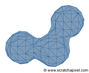
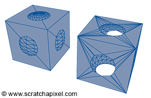
Implicit surfaces are very useful in modeling but are not as common as they once were. It is possible to create more complex shapes using implicit surfaces (implicit primitives such as spheres, cubes, cones, etc., combined through Boolean operations), a technique known as constructive solid geometry (or CSG). Metaballs, invented in the early 1980s by Jim Blinn, represent another form of implicit geometry used to create organic shapes.
The challenge with implicit surfaces is that they are not easy to render. Although it's often possible to ray trace them directly (by computing the intersection of a ray with an implicit surface using an algebraic approach, as explained earlier), they must first be converted to a mesh. This conversion process is not as straightforward as with NURBS or subdivision surfaces and requires a special algorithm, such as the marching cubes algorithm proposed by Lorensen and Cline in 1987. This conversion can potentially result in heavy meshes.
For more detail on these topics, check the section on Geometry.
Triangle as the Rendering Primitive
In this series of lessons, we will study an example of an implicit surface with the ray-sphere intersection test. We will also examine a parametric surface, the Utah teapot, which uses Bezier surfaces. However, most rendering APIs generally convert different geometry types to a triangular mesh and render this mesh. This approach has several advantages. Supporting multiple geometry types such as polygonal meshes, implicit, or parametric surfaces requires writing a ray-object routine for each supported surface type. This necessitates more code (with its obvious disadvantages) and makes it challenging to integrate these routines into a general framework, often resulting in decreased performance of the render engine.
Keep in mind that rendering encompasses more than just rendering 3D objects. It also needs to support features such as motion blur, displacement, etc. Having to support various geometry surfaces means that each one needs to work with the entire set of supported features, which is much more difficult than if all surfaces are converted to the same rendering primitive, allowing all features to work with this single primitive only.
Generally, better performance is achieved by limiting the code to rendering one primitive only, as this allows focusing all efforts on rendering this single primitive efficiently. Triangles have generally been the preferred choice for ray tracing. Extensive research has been conducted to find the best possible algorithm for computing the intersection of a ray with a triangle, aiming for the fastest execution, least memory usage, and most stability. Other rendering APIs, such as OpenGL, also render triangles exclusively, even though they don't use the ray tracing algorithm. Modern GPUs are generally designed and optimized for a single type of rendering based on triangles. Someone humorously noted:
Because current GPUs are designed to work with triangles, people use triangles, and so GPUs only need to process triangles, leading to their design focusing solely on triangles.
Limiting to one primitive allows building common operations directly into the hardware, making it highly efficient at performing these operations. Triangles are beneficial for various reasons, including their coplanarity, ease of subdivision, indivisibility, and the simplicity of interpolating texture coordinates across them. However, this does not mean that GPUs could not be designed to render other kinds of primitives efficiently (such as quads).
Can I use quads instead of triangles?
While the triangle is not the only primitive used for rendering, the quad can also be employed. Modeling or surfacing algorithms generating subdivision surfaces work with quads, making them common in 3D models. If quads could be rendered as efficiently as triangles, it would obviate the need for triangulation. Even in ray tracing, quads can sometimes be preferable to triangles, besides avoiding unnecessary triangulation for models already composed of quads. Ray-tracing quads will be addressed in the advanced section on ray tracing.
A 3D Scene Is More Than Just Geometry
However, a 3D scene encompasses more than just geometry. While geometry is a critical element, a camera is also needed to view the scene. Thus, a scene description typically includes a camera. Moreover, a scene without light would appear black, necessitating the inclusion of lights. In rendering, all this information (the geometry, camera, and lights) is contained within a file called the scene file. The content of the 3D scene can also be loaded into the memory of a 3D package such as Maya or Blender. In such cases, when a user initiates rendering, a special program or plugin processes each object in the scene, along with each light, and exports everything (including the camera) directly to the renderer. Additionally, the renderer requires certain extra information, such as the resolution of the final image, typically referred to as global render settings or options.
Summary
What you should remember from this chapter is that understanding the components of a scene is essential before creating an image of that 3D scene. A scene needs to contain three things: geometry (one or more 3D objects), lights (without which the scene would be black), and a camera, to define the viewing perspective. While various techniques can describe geometry (polygonal meshes, NURBS, subdivision surfaces, implicit surfaces, etc.), and each can be rendered directly using the appropriate algorithm, supporting one rendering primitive is simpler and more efficient. In ray tracing and on modern GPUs, the triangle is the preferred rendering primitive. Thus, geometry is generally converted to triangular meshes before rendering.