A Light Simulator
Reading time: 19 mins.We concluded the previous chapter with the assertion that ray tracing surpasses rasterization in simulating essential and prevalent shading and lighting effects, such as reflections and soft shadows. The inability to replicate these effects results in images lacking the photo-realism we aim for. Before delving deeper into this subject, let's examine some real-world images to gain a better understanding of these effects.
Reflection

When light interacts with a perfect mirror-like surface, it is reflected back into the environment in a predictable direction. This new direction can be calculated using the law of reflection. Analogous to a tennis ball rebounding off the ground, a light ray alters its direction upon contacting a surface. The reflected direction of this ray mirrors the incident direction around the normal at the point of contact. A more formal definition of the law of reflection states that the angle of reflection of a ray departing from a surface equals the angle of incidence at which the incoming ray strikes the surface. The accompanying image illustrates that the angle between the normal and the incident vector is equal to the angle between the normal and the reflected vector. It's important to note that although the image uses a water surface as an example of a reflective surface, water and glass are significantly less reflective than metals.
Transparency

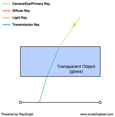
Transparent objects, such as a glass pane, reflect and refract light. The term "transmitted" is often used interchangeably with "refracted," though they convey slightly different meanings. "Transmitted" implies that a portion of the incident light enters the object on one side and exits on the opposite side, enabling us to see through windows, for instance. Upon contact with the surface of a transparent object, light changes direction, a phenomenon known as refraction. Refraction describes the bending of light rays as they move from one transparent medium, like air, to another, such as water or glass, regardless of the direction of travel. The direction of refraction can be determined using Snell's law. The Fresnel equations specify the proportions of light that are reflected and refracted. These equations play a crucial role in rendering. The diagram shows a primary ray passing through a glass block: it is refracted upon entry, travels through the glass, is refracted again upon exit, and finally impacts the surface beneath. If an object were present on that surface, this is what we would perceive through the glass.
Glossy or Specular Reflection

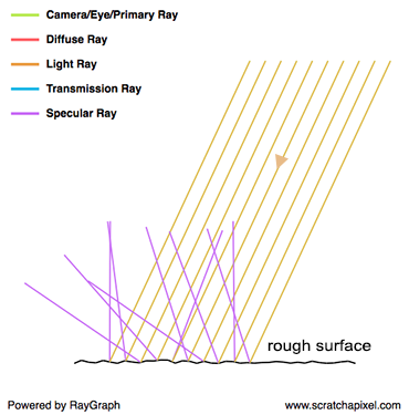
A glossy reflection is a material that is not perfectly reflective (like a mirror) nor perfectly diffuse. It is somewhere in between, where this "in-between" can either be anywhere between almost perfectly reflective (as in the case of a mirror-like surface) and almost perfectly diffuse. The glossiness of a surface is also sometimes referred to as its roughness (the two terms are antonymous) and specular reflection is often used instead of glossy reflection. You will often come across these two terms in computer graphics. Why do we speak of roughness then? To behave like a mirror, the surface of an object needs to be perfectly smooth. While many objects may appear flat and smooth in appearance (with the naked eye), looking at their surface under a microscope, reveals a very complex structure, which is not flat or smooth at all. In computer graphics we often like to describe rough surfaces, using the image of a surface made of lots of microfacets, where each one of these microfacets is oriented in a slightly different direction and acts on its own as a perfect mirror. As you can see in the adjacent image, when light bounces off from one of these facets, it is reflected in a slightly different direction than the mirror direction. The amount of variation between the mirror direction and the ray outgoing direction depends on how strongly the facets deviate from an ideally smooth surface. The stronger the deviation, the greater the difference, on average, between the ideal reflection direction and the actual reflection direction. Visually, rather than having a perfect image of the environment reflected off of a mirror-like surface, this image is slightly deformed (or blurred if you prefer). We have all seen how ripples caused by a pebble thrown into the water, change the sharp image reflected by a perfectly still water surface. Glossy reflections are similar to that: a perfect reflection deformed or blurred by the microscopic irregularities of the surface.
In computer graphics, we often speak of scattering. Because rather than being all reflected in the same direction, rays are scattered in a range of directions around the mirror direction (as shown in the last image on the right).
Diffuse Reflection

On the other extreme of a perfectly reflective surface, is the concept of diffuse surfaces. When we talked about specular reflection, we mentioned that light rays were scattered around the mirror direction. But for diffuse surfaces, rays are scattered even more, in fact so much, that they are reflected in all sorts of random directions. Incident light is equally spread in every direction above the point of incidence and as a result, a diffuse surface appears equally bright from all viewing directions (again that's because the incident light is equally spread in every direction as a result of being strongly scattered). Two things can cause a surface to be diffuse: the surface can either be very rough or made up of small structures (such as crystals). In the latter case, rays get trapped in these structures and are reflected and refracted by them a great number of times before they leave the surface. Each reflection or refraction with one of these structures changes the light direction, and it happens so many times that when they finally leave the surface, rays have a random direction. What we mean by random is that the outgoing direction does not correlate whatsoever with the incident direction. Or to put it differently, the direction of incidence does not affect the light rays' outing directions (which is not the case of specular surfaces), which is another interesting property of diffuse surfaces.
Subsurface Scattering

Subsurface scattering is the technical term for translucency. Translucent surfaces are those that are neither completely opaque nor entirely transparent. However, the reason objects appear translucent is not primarily due to transparency. This effect is observable in materials such as wax, jade, marble, or thin layers of organic material (e.g., skin, leaves) when they are strongly illuminated from behind. Translucency results from light traveling through the material, changing directions along its path, and exiting the object at a different location and direction than its point and direction of incidence. Simulating subsurface scattering is complex.
Indirect Diffuse

Certain surfaces of the ornamental object depicted in the adjacent image do not face any direct light source. They are neither facing the sun nor the sky (which can be considered a large light source). Yet, these surfaces are not completely dark. This phenomenon occurs because the floor, directly illuminated by the sun, reflects light back into the environment. Some of this light eventually illuminates parts of the object that are not receiving direct sunlight. Since the surface receives light emitted by sources such as the sun indirectly (through other surfaces), this is referred to as indirect lighting.
Indirect Specular or Caustics
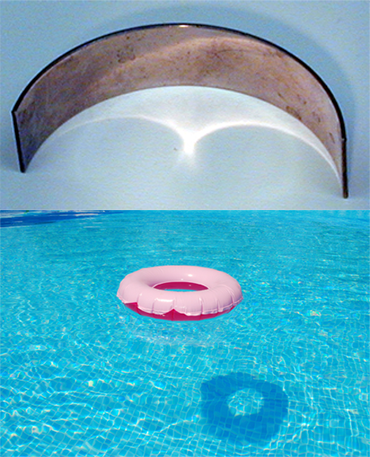
Similar to how diffuse objects reflect light that illuminates other objects in their vicinity, reflective objects can also indirectly illuminate other objects by redirecting light to different parts of their environment. Lenses or water surface waves concentrate light rays into specific lines or patterns, known as caustics. This effect is familiar to many, such as the patterns of light at the bottom of a sunlit pool. Caustics are also frequently observed when light reflects off the surfaces of disco balls, through windows in summer, or when a strong light is projected onto a glass object.
Soft Shadows
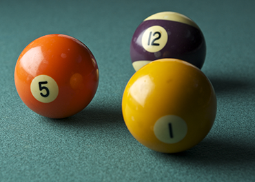
Most of the effects described thus far relate to an object's material properties. Soft shadows, on the other hand, are unrelated to materials. Simulating them is solely a geometric problem, involving the shapes, sizes, and spatial relationships of objects and light sources.
If you are curious about how all these effects can be simulated, do not worry. We will explore them in due time. At this point in the lesson, it is crucial to examine some real-world images and analyze the lighting/shading effects present. This will aid us in reproducing these effects later.
Remember from this chapter that a diffuse surface appears equally bright from all viewing directions, whereas the brightness of a specular surface varies with the viewing direction. Thus, we describe diffuse interaction as view-independent and specular interaction as view-dependent.
Light Transport and Shading: Two Related But Different Problems
The reason we've been reviewing these effects is for you to realize two things:
-
The appearance of objects depends solely on how light interacts with matter and travels through space.
-
These effects can be broadly categorized into two groups:
-
Some effects pertain to the appearance of objects.
-
Others relate to the amount of light an object receives.
Reflection, transparency, specular reflection, diffuse reflection, and subsurface scattering fall into the first category, which concerns shading—what gives an object its appearance. The second category, involving indirect diffuse, indirect specular, and soft shadows, pertains to light transport—how light is transferred from surface to surface after interacting with various materials.
Shading examines the interaction between light and matter. It encompasses everything that happens to light from the moment it reaches an object to the moment it departs.
Light transport, on the other hand, studies the journey of light as it bounces from surface to surface. It explores how light is reflected off various surfaces, how the nature of this reflection changes with the material (e.g., diffuse, specular), where light travels, whether it's obstructed by any geometry, and the impact of the obstructing geometry's shape on the light received by an object. Broadly, light transport focuses on the paths light rays follow as they move from a light source to the observer (termed flight paths).
-
It's important to note that the line between shading and light transport is quite fine. In the real world, no distinct separation exists—it's all about light's journey and the various paths it takes due to the objects it encounters. However, distinguishing between the two is practical in computer graphics because they cannot be efficiently simulated with the same approach. Let's delve into why.
If it were possible to replicate the world down to the atomic level in a computer program and define basic rules for light's interaction with atoms, we could simply wait for light to bounce around until it reached our eyes to create a perfect image. Ideally, such a program would be perfect, but it's currently unfeasible with our technology. Even with sufficient memory to model the world at an atomic scale, the computational power required to simulate the countless photons interacting with matter before reaching the observer would be immense, far beyond current capabilities. Thus, a different approach is necessary. Identifying the most time-consuming process reveals that while light's straightforward path from one surface to another is simple, the complex interactions occurring when light meets a surface would be the primary simulation challenge.
Therefore, in computer graphics, we differentiate between shading and light transport. Shading involves designing mathematical models that approximate light-matter interactions much faster than physical simulations. Meanwhile, simulating light's path as it travels from surface to surface is manageable, as these transitions are less complex. This distinction facilitates the development of strategies tailored to address both shading and light transport independently.
While simulating light transport is simpler than modeling light-matter interactions, it's not without its challenges. Certain types of inter-reflection, such as caustics, are particularly difficult to simulate (which we will discuss in the next chapter). Although creating effective models for light interaction is challenging, devising a competent light transport algorithm presents its own set of difficulties, as we will explore in subsequent discussions.
Global Illumination
But let's take a step back. While you might think (it's often a misconception) that most surfaces are visible because they receive light directly from a light source, there are about as many situations (if not more) where light only becomes visible as a result of being illuminated indirectly by other surfaces. Look around you and compare the number of objects or the ratio between areas that are directly exposed to a light source (the sun, artificial lights, etc.) and those not directly exposed but receive light reflected by another surface. Indirect lighting plays such an important role in the world as we see it, that without simulating it, it's challenging to achieve photo-realistic images. When rendering can simulate both direct and indirect lighting effects, we refer to it as global illumination. Ideally, in lighting, and more generally in rendering, we aim to simulate every possible lighting scenario. A scenario is defined by the shape of the objects in the scene, their material, the number and type of lights (be it the sun, a light bulb, or a flame), their shape, and finally, how objects are scattered throughout space (which influences how light travels from surface to surface).
In CG, we differentiate between direct and indirect lighting. If you don't simulate indirect lighting, you can still see objects in the scene due to direct lighting, but if you don't simulate direct lighting, the image will obviously be black (in the past, direct lighting was also referred to as local illumination in contrast to global illumination, which is the illumination of surfaces by other surfaces). But why wouldn't we simulate indirect lighting anyway?
Primarily because it's slow and/or not necessarily easy to do. As we will detail in the next chapter, light can interact with many surfaces before it reaches the eye. Considering ray tracing for now, as we also explained, what is most expensive to compute in ray tracing is the ray-geometry intersection test. The more surface interactions you need to simulate, the slower the rendering. With direct lighting, you only need to find the intersection between the primary or camera rays (the rays traced from the camera) and the geometry in the scene, and then cast a ray from each one of these intersections to the lights in the scene (this ray is called a shadow ray). This is the least we need to produce an image (we could ignore shadows, but shadows are a very important visual clue that helps us figure out where objects are in space, particularly in relation to each other, and also helps to recognize objects' shapes, etc.). To simulate indirect lighting, many more rays need to be cast into the scene to "gather" information about the light that bounces off other objects' surfaces. Simulating indirect lighting in addition to direct lighting requires not twice as many rays (compared to the number used for direct lighting) but orders of magnitude more (to achieve a visually accurate and good result). Since the ray-object intersection test is expensive, as mentioned before, the more rays, the slower the render. To complicate matters, when we compute indirect lighting, we cast new rays from a point P in the scene to gather information about the light reflected by other surfaces towards P. Interestingly, this also requires computing the amount of light arriving at these other surfaces, which means that for each one of the surfaces we need to compute the amount of light reflected towards P, we also need to compute direct and indirect lighting, spawning even more rays. This effect is recursive, making indirect lighting a potentially very expensive effect to simulate. It doesn't just make your render twice as long but many times longer.
Why is it difficult? It's straightforward if you use ray tracing (but eventually expensive). Ray tracing, as we will explain in the next paragraph, is a natural way of thinking about and simulating how light flows in the natural world. It's easy from a simulation standpoint because it offers a simple way to "gather" information about light reflected off surfaces in the scene. If your system supports computing the intersection of rays with geometry, then you can use it to either solve the visibility problem or simulate direct and indirect lighting. However, if you use rasterization, how do you gather that information? It's a common misconception that ray-tracing is necessary to simulate indirect lighting, but this isn't true. Many alternatives to ray tracing exist for simulating indirect lighting (point cloud-based methods, photon maps, virtual point lights, shadow maps, etc.). Radiosity is another method for computing global illumination. It's not used as much these days but was very popular in the 80s and early 90s; these methods also have their advantages and can be, in some situations, a good (if not better) alternative to ray tracing. However, again, the "easy" way is to use ray tracing if your system supports it.
As mentioned before, compared to some other methods, ray tracing can be slow when simulating indirect lighting effects. Furthermore, while ray tracing is appealing for many reasons, it also has its own set of issues (besides being computationally expensive). For example, noise is one of them. Interestingly, some of the alternative methods to ray tracing we discussed simulate indirect lighting and produce noise-free images (often at the expense of being biased - we will explain what that means in the lesson on Monte Carlo ray tracing but, in short, it means that mathematically, we know the solution computed by these algorithms doesn't converge to the true solution (as it should), which is not the case with Monte Carlo ray tracing.
Furthermore, we will show in the next chapter devoted to light transport that some lighting effects are very difficult to simulate because, while it's more efficient in rendering to simulate the path of light from the eye back to light sources, in some specific cases, this approach is not efficient at all. We will show what these cases are in the next chapter, but within the context of the problem at hand here, it means that naive "backward" ray tracing is just not the solution to everything: while being efficient at simulating direct lighting and indirect diffuse effects, it is not a very efficient way of simulating other specific lighting effects such as indirect specular reflections (we will show why in the next chapter). In other words, unless you decide that brute force is okay (you generally do until you realize it's not practical to work with), you will quickly realize that "naive" backward ray tracing is clearly not the solution to everything, and you might look for alternative methods. Photon maps are a good example of a technique designed to efficiently simulate caustics (a mirror reflecting light onto a diffuse surface, for example — which is a form of indirect specular reflection) which are very hard or computationally expensive to simulate with ray tracing.
Why is ray-tracing better than rasterization? Is it better?
We have already provided some information on this question in the previous paragraph. Ray-tracing offers a more natural way of simulating how light flows in the real world, making it arguably the most straightforward approach to simulating lighting, especially compared to methods such as rasterization. Unlike dealing with multiple methods to solve visibility and lighting issues, ray tracing addresses both, presenting a significant advantage. Essentially, you need to find the most efficient way to compute the intersection of rays with geometry and reuse that code for both visibility and lighting. Simple and easy. Using rasterization for visibility requires another method to compute global illumination (GI). While computing GI without ray tracing isn't impossible, it necessitates a mix of techniques, which is less elegant and a primary reason why many prefer ray tracing.
However, ray tracing is not without its problems. Although a naive implementation of ray tracing is straightforward, an efficient one demands considerable effort. Despite today's computers being significantly more powerful than those of a decade ago, the increased complexity of scenes rendered means that rendering times remain long (see note below).
This is known as Blinn's Law or the paradox of increasing performance. "What is Blinn's Law? Most are familiar with Moore's law, which predicts that the number of transistors on a chip will double approximately every two years, implying steadily increasing computational power. For computer graphics, this means potential benefits from increasing computational power. Blinn's law suggests that if an animation studio invests ten hours of computation time per frame of animation today, they will invest ten hours per frame ten years from now, regardless of advances in processing power." (courtesy of www.boxtech.com).
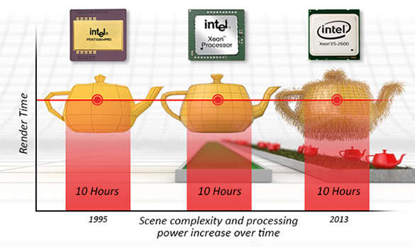
Therefore, aggressive code optimization is necessary, especially in production environments. Aside from the technical challenges, a main drawback of ray tracing is the noise (or variance) it introduces to the image and the complexity of simulating certain lighting effects, such as caustics, when using backward ray tracing. A brute-force solution—increasing the number of rays—improves simulation quality but at greater computational cost. Consequently, much research in rendering focuses on addressing these issues. Light transport algorithms, as we will discuss in the next chapter, explore various ways to simulate light transport. Ray tracing can also be combined with other techniques to efficiently simulate challenging lighting effects that are difficult to achieve with ray tracing alone.
In conclusion, there is little doubt that all rendering solutions, including those for real-time technologies and video games, will eventually adopt ray tracing. It's only a matter of time. The latest generation of GPUs already supports hardware-accelerated ray tracing (e.g., RTX), enabling real-time or near real-time frame rates, though this still depends on scene complexity (number of triangles/quads, number of lights, etc.).