Perspective Projection
Reading time: 9 mins.In the previous chapter, we discussed that the rendering process could be viewed as a two-step process:
-
Projecting 3D shapes onto the surface of a canvas and determining which parts of these surfaces are visible from a given point of view.
-
Simulating the way light propagates through space, which, combined with a description of how light interacts with the materials objects are made of, will give these objects their final appearance (their color, their brightness, their texture, etc.).
In this chapter, we will focus exclusively on the first step in more detail, specifically explaining how each of these problems (projecting the objects' shapes onto the surface of the canvas and the visibility problem) is typically solved. While many solutions may exist, we will only explore the most common ones. This is merely an overview. Each method will be studied in separate lessons, and an implementation of these algorithms will be provided (in a self-contained C++ program).
Going from 3D to 2D: The Projection Matrix

An image is essentially a representation of a 3D scene on a flat surface: the surface of a canvas or a screen. As explained in the previous chapter, to create an image that appears realistic to our brains, we need to simulate how an image of the world is formed in our eyes. The principle is quite straightforward. We simply extend lines from the corners of the object towards the eye and find where these lines intersect with a flat surface perpendicular to the line of sight. By connecting these points to draw the edges of the object, we achieve a wireframe representation of the scene.
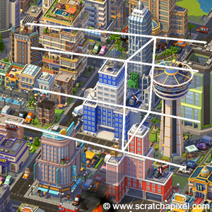
It is important to note that this method of constructing an image is, in a way, an entirely arbitrary method of flattening a three-dimensional world onto a two-dimensional surface. The technique we just described results in what is known in drawing as a one-point perspective projection, and this is generally the approach used in CG because it mimics how the eyes and cameras work (cameras were designed to produce images similar to those our eyes create). However, in the art world, there are no limitations to creativity. You can, for example, create images with multiple points of perspective (two, three, four, etc.).
One of the key visual characteristics of this type of projection is that an object appears smaller as it moves further away from the eye (the rear edges of a box appear smaller than the front edges). This effect is known as foreshortening.
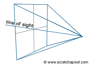
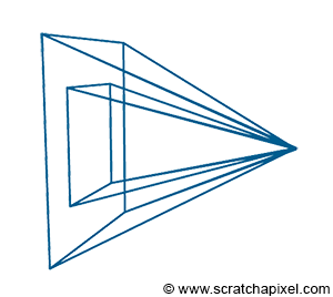
There are two important aspects to note about this type of projection. First, the eye is at the center of the canvas, meaning the line of sight always passes through the middle of the image (Figure 2). It is also crucial to understand that we can change the size of the canvas. This change becomes more comprehensible when we illustrate the viewing frustum (Figure 3). The frustum is the pyramid formed by tracing lines from each corner of the canvas towards the eye and extending these lines further into the scene. It is also known as the viewing frustum or viewing volume. Clearly, only objects within the volume of this pyramid are visible to the camera. Adjusting the size of the canvas can either expand or reduce this volume. The larger the volume, the more of the scene we capture. This effect is analogous to changing the focal length of photographic lenses. Another way to phrase this is that altering the canvas size modifies the field of view.
An interesting phenomenon occurs when the canvas shrinks to an infinitesimally small size: the lines forming the frustum become parallel (orthogonal to the canvas). While this is physically impossible, it is feasible in the virtual realm of computing. In this scenario, what emerges is known as an orthographic projection. Notably, orthographic projection is a type of perspective projection where the canvas size is virtually zero. This effectively eliminates the foreshortening effect, preserving the sizes of object edges when projected onto the screen.
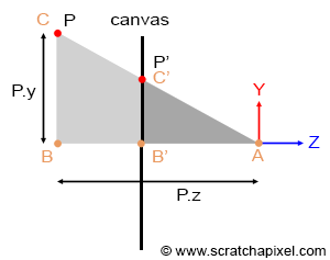
Geometrically, determining the intersection point of these lines with the screen is remarkably straightforward. Observing the adjacent figure (where P is the point projected onto the canvas, and P' represents this projected point), it is evident that the angles \\(\\angle ABC\\) and \\(\\angle AB'C'\\) are identical. Here, A represents the eye, AB is the z-axis distance to point P (P's z-coordinate), and BC is the y-axis distance to point P (P's y-coordinate). B'C' denotes the y-coordinate of P', and AB' signifies the z-coordinate of P' (also the distance from the eye to the canvas). When two triangles share an angle, they are considered similar. An intriguing property of similar triangles is that the ratios of the lengths of their corresponding sides remain constant. Applying this principle, we can express:
$${ BC \over AB } = { B'C' \over AB' }$$Assuming the canvas is located one unit away from the eye (thus, AB' equals 1, for simplicity), and substituting AB, BC, AB', and B'C' with their respective coordinates, we derive:
$${ BC \over AB } = { B'C' \over 1 } \rightarrow P'.y = { P.y \over P.z }.$$In essence, to ascertain the y-coordinate of the projected point, one merely divides the point's y-coordinate by its z-coordinate. Similarly, to determine the x-coordinate of P':
$$P'.x = { P.x \over P.z }.$$This relationship, known as the perspective divide or z-divide, is fundamental in computer graphics. If stranded on a desert island with only one computer graphics principle to remember, it would likely be this equation.
In computer graphics, this operation is typically performed using what is called a perspective projection matrix. This matrix, when applied to points, projects them onto the screen. In the following lesson, we will delve into the workings of this matrix, explaining its mechanics and how to construct and apply it.
However, the necessity for perspective projection varies based on the technique employed to address the visibility problem. As we will explore in the second part of this chapter, algorithms for tackling the visibility issue fall into two main categories:
-
Rasterization
-
Ray-tracing
Algorithms of the first category rely on projecting \(P\) onto the screen to compute \(P'\). For these algorithms, the perspective projection matrix is, therefore, needed. In ray tracing, rather than projecting the geometry onto the screen, we trace a ray passing through \(P'\) and search for \(P\). With this approach, projecting \(P\) is unnecessary because \(P'\) is already known; thus, in ray tracing, the perspective projection is technically not needed (and is therefore never used).
We will study the two algorithms in detail in the next chapters and lessons. However, understanding the difference between them and how they work at this point is important. As explained before, to project the geometry onto the canvas surface, \(P\) is projected along an "implicit" line (implicit because we never really need to construct this line as we do with ray tracing) connecting \(P\) to the eye. You can envision the process as moving a point along that line from \(P\) to the eye until it lies on the canvas. That point would be \(P'\). In this approach, you know \(P\), but \(P'\) is unknown. It is computed using the projection method. Conversely, you can also look at the problem from another perspective. For any point on the canvas (say \(P'\) - which, by default, we will assume is at the center of the pixel), there may be a point \(P\) on the geometry's surface that projects onto \(P'\). The solution to this problem is to explicitly create a ray from the eye to \(P'\), extend or project this ray down into the scene, and determine if this ray intersects any 3D geometry. If an intersection occurs, the intersection point is \(P\). This explanation should help clarify the difference between rasterization (knowing \(P\), computing \(P'\)) and ray tracing (knowing \(P'\), searching for \(P\)).
The advantage of rasterization over ray tracing is primarily speed. Computing the intersection of rays with geometry is a computationally intensive operation. This intersection time also increases linearly with the volume of geometry in the scene, as we will discuss in an upcoming lesson. Conversely, the projection process is incredibly straightforward, based on basic mathematical operations (multiplications, divisions, etc.), and can be significantly optimized (especially with specialized hardware, such as GPUs). Graphics cards predominantly use an algorithm based on the rasterization approach (which is one reason they can render 3D scenes so quickly, at interactive frame rates). When utilizing real-time rendering APIs like OpenGL or DirectX, handling the projection matrix becomes necessary. Even if interested solely in ray tracing, understanding the projection matrix is valuable for historical reasons: it's a crucial technique in rendering and the most common method for producing real-time 3D computer graphics. Additionally, interacting with the GPU and real-time rendering APIs, which do not compute this matrix for you, is likely; thus, you will need to do so yourself.
The concept of rasterization is crucial in rendering. As we've learned in this chapter, projecting \(P\) onto the screen involves dividing the point's \(x\) and \(y\) coordinates by its \(z\)-coordinate. Initially, all coordinates are real numbers—floats, for instance—meaning \(P'\) coordinates are also real numbers. However, pixel coordinates must be integers. Therefore, to store the color of \(P'\) in the image, we need to convert its coordinates to pixel coordinates—from floats to integers. This process is described as converting the point's coordinates from screen space to raster space. More information on this process will be provided in the lesson on rays and cameras.
The next lessons are devoted to studying the construction of the orthographic and perspective matrices and how to use them in OpenGL to display images and 3D geometry.